System Operation Description:
Use this procedure under the following situation:
The circuit for the diagnostic enable switch is suspected of incorrect operation.
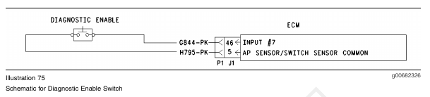
Diagnostic Enable Switch
The diagnostic enable switch is used to prompt diagnostic flash codes on the check engine lamp. For more information, refer to the “Flashing Out Diagnostic Flash Codes” section in Troubleshooting, “Check Engine Lamp Circuit – Test”. If the “Diagnostic Enable Switch” parameter is programmed to “None” (default), then the feature is not used. If the “Diagnostic Enable Switch” parameter is programmed to J1/P1:46, then the feature is available and the switch circuit should be connected to J1/P1:46 ECM vehicle harness connector.

Test Step 1. Check the Status of the “Diagnostic Enable”
A. Connect the electronic service tool to the data link connector.
B. Turn the key switch to the On position.
C. Observe the status for “Diagnostic Enable” while the diagnostic enable switch is operated in the
On position and the Off position.
Note: If the status for the “Diagnostic Enable” indicates “Not Installed”, then the “Diagnostic Enable” parameter has not been programmed.
Expected Result:
The status for “Diagnostic Enable” should indicate “On” when the switch is in the On position. The status for “Diagnostic Enable” should indicate “Off” when the switch is in the Off position.
Results:
• OK – The switch is operating normally.
Repair: If the check engine lamp is not operating correctly, refer to Troubleshooting, “Check Engine
Lamp Circuit – Test”.
STOP.
• Not OK – The ECM is not reading the switch status change. Proceed to Test Step 2.
Test Step 2. Determine the Configuration of the Diagnostic Enable Switch
A. Determine if the wiring for the diagnostic enable switch is wired directly to the ECM or through the J1939 data link.
B. Verify that the “Diagnostic Enable” parameter is programmed to reflect the proper wiring.
Expected Result:
The diagnostic enable switch is wired directly to the ECM.
Results:
• OK – The diagnostic enable switch is wired directly to the ECM. Proceed to Test Step 3.
• Not OK – The diagnostic enable switch is wired through the J1939 data link.
Repair: Verify that the “Diagnostic Enable” parameter is programmed to “J1939 – Body Controller”, “J1939 – Cab Controller”, or “J1939 – Instrument Cluster”.
Refer to Troubleshooting, “Powertrain Data Link Circuit – Test”.
STOP.
Test Step 3. Check the Electrical Connectors and the Wiring
A. Thoroughly inspect the J1/P1 ECM connector, the connectors, and the firewall bulkhead connectors. Refer to Troubleshooting, “Electrical Connectors – Inspect” for details.
B. Perform a 45 N (10 lb) pull test on each of the wires in the ECM connector that are associated with the suspect switch circuit.
C. Check the ECM connector (Allen Head Screw) for the proper torque of 6.0 N·m (55 lb in).
D. Check the harness and the wiring for abrasion and pinch points from the battery to the ECM. Then, check from the ignition key switch to the ECM.
Refer to Illustration 76 for terminal locations for the ECM.
Expected Result:
All connectors, pins, and sockets are completely coupled and/or inserted, and the harness and wiring should be free of corrosion, abrasion or pinch points.
Results:
• OK – Proceed to Test Step 1.
• Not OK – Repair the wiring and connectors or replace the wiring or the connectors. Ensure that all of the seals are properly connected. Verify that the repair eliminates the problem. STOP.
Test Step 4. Check the Switch Circuit for the ECM
A. Turn the key switch to the OFF position.
B. Install a 140-2266 Cable (Seventy-Pin Breakout) between the J1 and P1 ECM connectors.
C. Fabricate a jumper wire 100 mm (4 inch) long.
Crimp a Deutsch pin to both ends of the wire.
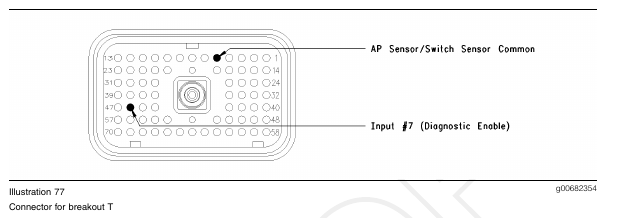
D. Insert the jumper wire into terminal 46 (Diagnostic Enable Switch Input) of the breakout T. Connect the other end of the jumper wire to terminal 5 (AP Sensor/Switch Sensor Common) of the breakout T.
E. Turn the key switch to the On position.
F. While the status for “Diagnostic Enable” is monitored, remove the jumper wire and insert the jumper wire from terminal 5.
Expected Result:
The status for “Diagnostic Enable” is “On” when the jumper wire is in place. The status for “Diagnostic Enable” is “Off” when the jumper wire is removed.
Results:
• OK – The ECM is functioning properly at this time.
Repair: Remove the breakout T and reconnect the J1/P1 ECM connector.
Proceed to Test Step 5.
• Not OK – The ECM is not functioning properly.
Repair: Temporarily connect a test ECM. If the problem is resolved with the test ECM, install the suspect ECM. If the problem returns with the suspect ECM, replace the ECM.
Verify that the repair eliminates the problem.
STOP.
Test Step 5. Insert a Jumper Wire at the Switch
A. Turn the key switch to the OFF position.
B. Fabricate a jumper wire 100 mm (4 inch) long.
Crimp a Deutsch pin to each end of the wire.
C. Insert the jumper wire between the two terminals of the diagnostic enable switch.
D. Turn the key switch to the ON position.
E. While the status for “Diagnostic Enable” is monitored, remove the jumper wire and insert the jumper wire at the switch terminals.
Expected Result:
The status for “Diagnostic Enable” is “On” when the jumper wire is in place. The status for “Diagnostic Enable” is “Off” when the jumper wire is removed.
Results:
• OK
Repair: Replace the diagnostic enable switch.
Verify that the repair eliminates the problem.
STOP.
• Not OK – There is a problem in the wire harness between the diagnostic enable switch and the ECM. Proceed to Test Step 6.
Test Step 6. Insert a Jumper Wire at the Bulkhead Connector
A. Turn the key switch to the OFF position.
B. Fabricate a jumper wire 100 mm (4 inch) long.
Crimp a Deutsch pin to each end of the wire.
C. Locate the suspect switch socket in the engine side of the ECM bulkhead connector.
D. Insert the wire jumper pin between the switch socket and the sensor common connection.
Install the jumper wire on the engine side of the ECM bulkhead connector.
E. Turn the key switch to the ON position.
F. While the status for “Diagnostic Enable” is monitored, remove the jumper wire and insert the jumper wire at the bulkhead connector.
Expected Result:
The status for “Diagnostic Enable” is “On” when the jumper wire is in place. The status for “Diagnostic Enable” is “Off” when the jumper wire is removed.
Results:
• OK – The problem is in the vehicle wiring between the bulkhead connector and the switch.
Inspect the vehicle wiring and then repair the vehicle wiring. Otherwise, send the vehicle to the OEM dealer for repair. Verify that the original condition is resolved. STOP.
• Not OK – The problem is in the vehicle wiring between the bulkhead connector and the ECM. Inspect the vehicle wiring and then repair the vehicle wiring. Otherwise, send the vehicle to the OEM dealer for repair. Verify that the original condition is resolved. STOP.