System Operation Description:
Most electrical problems are caused by poor connections. The following procedure will assist in detecting problems due to connectors. If a problem is found in an electrical connector, repair the connector and verify that the problem does not return. Do NOT cut connector wires unless terminals are being replaced. Repair the connectors with a 1U-5804 Crimp Tool. The wedges on the DT connectors are easily removed with a 147-6456 Removal Tool.
Intermittent electrical problems often disappear by disconnecting and reconnecting connectors. It is very important to check for diagnostic codes immediately before disconnecting a connector. Also check for diagnostic codes after reconnecting any connectors. If the status of a diagnostic code is changed due to disconnecting and reconnecting a connector, there are several possible reasons. The likely problems are loose or improperly crimped terminals, moisture, corrosion, or connectors not mated securely.
ALWAYS crimp the terminals on the wires with the 1U-5804 Crimp Tool. Do not solder the terminals.


Test Step 1. Check the Locking of the DT Connector (Deutsch) and Check the Lock Ring of the HD Style Connector (Deutsch)
A. Ensure that the connector is properly locked.
Also ensure that the two halves of the connector can not be pulled apart.
B. Verify that the latch tab of the connector is properly latched. Also verify that the latch tab of the connector returns to the locked position.
Expected Result:
The connector will securely lock. The connector and the locking mechanism are without cracks or breaks.
Results:
• OK – Proceed to Test Step 2.
• Not OK
Repair: Repair the connector or replace the connector, as required.
Verify that the repair eliminates the problem.
STOP.
Test Step 2. Check the Allen Head Screw on the ECM Connector
A. Ensure that the allen head screw is properly tightened. Be careful not to overtighten the screw and break the screw.
B. Do not exceed 6.0 N·m (55 lb in) of torque on the allen head screw.
Expected Result:
The ECM connector is secure and the allen head screw is properly torqued.
Results:
• OK – Proceed to Test Step 3.
• Not OK
Repair: Repair the connector or replace the connector, as required.
Verify that the repair eliminates the problem.
STOP.
Test Step 3. Perform a Pull Test on Each Wire Terminal Connection
A. Each terminal and each connector should easily withstand 45 N (10 lb) of pull and each wire should remain in the connector body. This test checks whether the wire was properly crimped in the terminal and whether the terminal was properly inserted into the connector.
B. The DT connectors use a green wedge to lock the terminals in place. Ensure that the green wedge is not missing and that the green wedge is installed properly on the DT connectors.
Note: Terminals should always be crimped onto the wires by using a crimp tool. Do not solder terminals.
Use the 1U-5804 Crimp Tool.
Expected Result:
Each terminal and each connector easily withstands 45 N (10 lb) of pull and each wire remains in the connector body.
Results:
• OK – Proceed to Test Step 4.
• Not OK
Repair: Repair the circuit.
Verify that the repair eliminates the problem.
STOP.
Test Step 4. Perform the “Wiggle Test” on Cat ET
A. Select the “Wiggle Test” from the diagnostic tests on Cat ET.
B. Press the “OK” button after you adhere to the warning.
C. Choose the appropriate group of parameters to monitor.
D. Press the “Start” button. Wiggle the wiring harness in order to reproduce intermittent problems.
E. If an intermittent problem exists, the status will be highlighted and an audible beep will be heard.
Expected Result:
No intermittent problems were indicated during the “Wiggle Test”.
Results:
• OK – Proceed to Test Step 5.
• Not OK
Repair: Repair the circuit.
Verify that the repair eliminates the problem.
STOP.
Test Step 5. Check Wires for Nicks or Abrasion in the Insulation
A. Carefully inspect each wire for signs of abrasion, nicks, or cuts.
The following areas are locations that should be checked:
• Exposed insulation
• Points of rubbing wire against the engine
• Points of rubbing wire against a sharp point
B. Check all of the hold down clamps for the harness in order to verify that the harness is properly clamped. Also check all of the hold down clamps for the harness in order to verify that the harness is not compressed by the clamp. Pull back the harness sleeves in order to check for a flattened portion of wire. The flattened portion of wire is caused by the clamp that holds the harness.
Expected Result:
The wires are free of abrasion, nicks, or cuts and the harness is properly clamped.
Results:
• OK – Proceed to Test Step 6.
• Not OK
Repair: Repair the wires or replace the wires, as required.
Verify that the repair eliminates the problem.
STOP.
Test Step 6. Check Connectors for Moisture or Corrosion

A. Ensure that the connector seals and the white sealing plugs are in place. If any of the seals or plugs are missing, replace the seal or plug. If necessary, replace the connector.
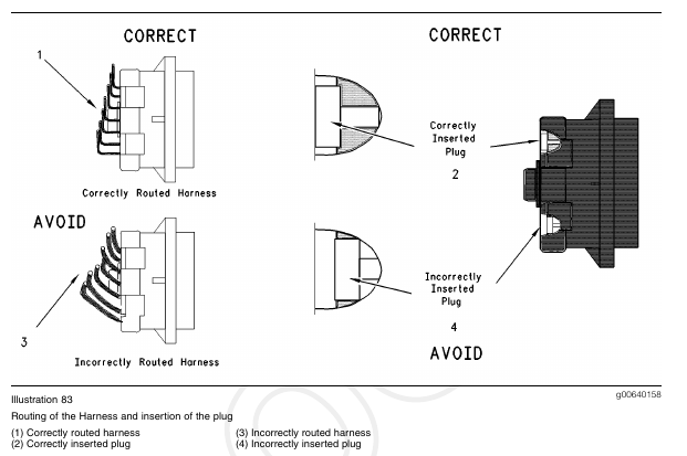
B. Check all of the wiring harnesses in order to verify that the harness does not make a sharp bend out of a connector. This will deform the connector seal and this will create a path for the entrance of moisture.
Thoroughly inspect the J1/P1 and J2/P2 ECM connectors for evidence of moisture entry.
Note: It is normal to see some minor seal abrasion on the ECM Connector seals. Minor seal abrasion will not allow the entry of moisture.
C. If moisture or corrosion is evident in the connector, the source of the moisture entry must be found and the source of the moisture entry must be repaired. If the source of the moisture entry is not repaired, the problem will reoccur. Simply drying the connector will not fix the problem. Likely paths for the entrance of moisture are illustrated in the following list:
• Missing seals
• Improperly installed seals
• Nicks in exposed insulation
• Improperly mated connectors
Moisture can also travel from one connector through the inside of a wire to the ECM Connector. If moisture is found in the ECM connector, thoroughly check all connectors and wires on the harness that connect to the ECM. The ECM is not the source of the moisture. Do not replace an ECM if moisture is found in either ECM connector.
Note: If corrosion is evident on the pins, sockets or the connector, use only denatured alcohol to remove the corrosion. Use a cotton swab or a soft brush to remove the corrosion. Do not use any cleaners that contain 1,1,1 trichloro-ethylene because 1,1,1 trichloro-ethylene may damage the connector.
Expected Result:
All of the connectors should be completely coupled and all of the seals should be completely inserted.
The harness and the wiring should be free of corrosion, abrasion or pinch points.
Results:
• OK – Proceed to Test Step 7.
• Not OK
Repair: Repair the connectors or wiring and/or replace the connectors or wiring. Ensure that all of the seals are properly in place and ensure that the connectors are completely coupled.
Verify that the repair eliminates the problem by running the engine for several minutes and by checking again for moisture. If moisture reappears, the moisture is wicking into the connector. Even if the moisture entry path is repaired, it may be necessary to replace the wires that have moisture. These wires may have moisture that is trapped inside the insulation.
Verify that the repair eliminates the problem.
STOP.
Test Step 7. Inspect the Connector Terminals
A. Verify that the terminals are not damaged. Verify that the terminals are properly aligned in the connector and verify that the terminals are properly located in the connector.
Expected Result:
The terminals are properly aligned and the terminals appear undamaged.
Results:
• OK – Proceed to Test Step 8.
• Not OK
Repair: Repair the terminals and/or replace the terminals, as required.
Verify that the repair eliminates the problem.
STOP.
Test Step 8. Check Individual Pin Retention into the Socket
Note: This is especially important for intermittent problems.
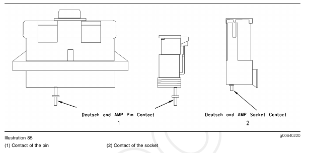
A. Use a new pin. Insert the pin into each socket one at a time in order to check for a good grip on the pin by the socket.
B. Use a new socket. Insert the socket over each pin one at a time in order to check for a good grip on the pin by the socket. The pins are located on the mating side of the connector.
C. The contact terminal should stay connected when the connector is held in the position shown in Illustration 85. The contact terminal is the pin or the socket.
Expected Result:
The pins and the sockets appear to be OK.
Results:
• OK – STOP.
• Not OK
Repair: Repair the terminals and/or replace the terminals.
Verify that the repair eliminates the problem.
STOP.