System Operation Description:
Use this procedure under the following situation:
One of the following diagnostic codes are active:
• 231-02 J1939 Data Incorrect
• 231-12 J1939 Device Not Responding
Also, use this procedure when a feature that uses the J1939 data link is not operating correctly. The following features can be configured to use the J1939 data link:
• “Adaptive Cruise Control Enable”
• “Fan Overide Switch”
• “Diagnostic Enable”
• “PTO On/Off Switch”
• “Remote PTO Set Switch”
• “Remote PTO Resume Switch”
• “PTO Engine RPM Set Speed Input A”
• “Two-Speed Axle Switch”
• “Cruise Control On/Off Switch”
• “Cruise Control Set/Resume/Accel/Decel Switch”
• “Cruise Control Pause Switch”
• “Clutch Pedal Position Switch”
• “Retarder Off/Low/Medium/High Switch”
• “Service Brake Pedal Position Switch #1”
• “Vehicle Speed Input”
• “Power Train Data Link”
Note: Use the electronic technician to view the “Configuration” screen in order to determine if any of these parameters are configured to use the J1939 data link. Some of the feature must use the J1939 data link if the components are installed. Features that must use the J1939 data link include the “Adaptive Cruise Control Enable”, “Cruise Control Pause Switch”, and the “Power Train Data Link”.
The following background information is related to this procedure:
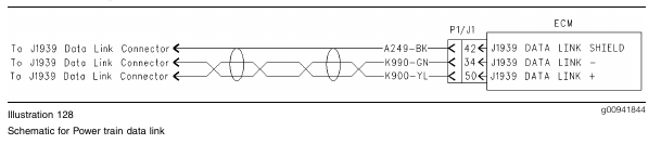
Power train Data Link
The power train data link is designed to offer electronically controlled Anti-Lock Brakes (ABS), traction control systems, and/or transmission controls. This is accomplished by a momentary reduction of engine rpm and/or engine torque, that is triggered by a signal from an off-engine control module for the ABS, the traction control, or the transmission. An off-engine control module is a control module that is not part of the Caterpillar engine control system.
Any combination of the following systems may be installed together on a vehicle:
• Traction Control
• Transmission Control
• ABS
The required components are installed at the OEM when the vehicle is built.
Power train data link sensors, off-engine control modules, and wiring are installed by the vehicle OEM. Refer to the vehicle OEM for questions that are related to these components.
Anti-Lock Brake Systems (ABS)
The “Power Train Data Link” may be used by an anti-lock brake system (ABS) in order to disable the engine retarder when the anti-lock brake control determines that the engine retarder should be disabled. This is usually achieved when the ABS system is active.
Traction Control Systems
Loss of traction is determined by sensors on the vehicle that are mounted near the wheels. These sensors are also used by the ABS system. Typically, a system with traction control includes Anti-Lock brakes.
Transmission Control
The following characteristics are determined by a vehicle speed sensor in the transmission:
• Transmission shift points
• Engine rpm
• Load
The sensors for power train control provide signals to the vehicle control module of the “Power Train Data Link”. The vehicle control module of the “Power Train Data Link” then communicates with the engine ECM. The engine ECM receives a request from the “Power Train Data Link”. The engine ECM responds by momentarily limiting the following characteristics:
• Engine rpm
• Torque
• Both Engine rpm and Torque
The presence of an active J1939 data link circuit can be determined by observing the “Power Train Status” screen on the electronic service tool. The status screen will display “Installed” if the proper software is installed in the ECM, and there is no action that is being requested at that time by any of the control modules on the data link.
If an action is being requested by one of the vehicle control modules, the display will indicate the control that is making the request (Traction Control or Transmission Control) or a combination of the two (Traction Control and Transmission Control). Power train control is also displayed in the upper right hand corner of the display status screen. This space is replaced by the low oil pressure indicator, when a condition of low oil pressure exists.
J1939 Data Link
SAE J1939 is standard on all engines.
Note: The wiring for the J1939 data link is a shielded twisted pair cable and the wiring is not serviceable. The wiring must be replaced when the wiring is damaged.
Test Step 1. Inspect Electrical Connectors and Wiring
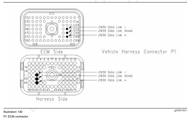
A. Thoroughly inspect the J1/P1 ECM connector, the firewall bulkhead connector, and the connectors for all components that utilize the J1939 data link. Refer to Troubleshooting, “Electrical Connectors – Inspect” for details.
B. Perform a 45 N (10 lb) pull test on each of the wires in the ECM connector that are associated with the J1939 data link.
Refer to Illustration 130.
C. Check the ECM connector (allen head screw) for the proper torque of 6.0 N·m (55 lb in).
D. Check the harness and wiring for abrasion and pinch points from the data link connectors back to the ECM.
Expected Result:
All connectors, pins, and sockets should be completely coupled and/or inserted and the harness and wiring should be free of corrosion, abrasion, or pinch points.
Results:
• OK – Proceed to Test Step 2.
• Not OK
Repair: Perform the following repair:
Repair the connectors or wiring and/or replace the connectors or wiring. Ensure that all of the seals are properly in place and ensure that the connectors are completely coupled.
Verify that the repair eliminates the problem.
STOP.
Test Step 2. Check for Active Diagnostic Codes
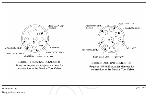
A. Connect the electronic service tool to the data link connector.
B. Turn the key switch to the ON position.
C. Monitor the active diagnostic code screen on the electronic service tool. Check and record active diagnostic codes.
Expected Result:
One of the following diagnostic codes is active:
• 231-02 J1939 Data Incorrect
• 231-12 J1939 Device Not Responding
Note: If the J1939 data link is not installed or the J1939 data link is not utilized, then all of the programmable parameters should be configured to reflect the actual wiring.
Results:
• OK – 231-02 and/or 231-12 is active. Proceed to Test Step 3.
• Not OK – None of the diagnostic codes are active. Proceed to Test Step 5.
Test Step 3. Verify that the J1939 Data Link is Utilized
A. Turn the key switch to the OFF position.
B. Verify that the J1939 data link is used for the power train or for switch inputs to the ECM.
Expected Result:
The J1939 data link is used for the power train or for switch inputs to the ECM.
Results:
• OK – The J1939 data link is utilized.
Repair: Verify that the suspect component is also utilizing the J1939 data link. Configure the ECM to reflect the actual wiring.
Proceed to Test Step 4.
• Not OK – The J1939 data link is not utilized.
Repair: Perform the following procedure:
1. Access the “Configuration” screen.
a. Change any parameter that is configured to use the J1939 data link to the correct option.
b. Select “None” if the option is not installed.
Note: If the “Adaptive Cruise Control Enable” parameter is “Enabled”, change the parameter to “Disabled”.
STOP.
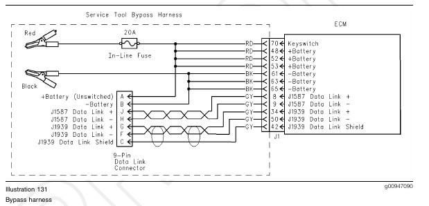
Test Step 4. Connect a Bypass Harness
A. Turn the key switch to the OFF position.
Note: This step is only applicable to service tools that use the communications adapter II.
B. Connect a bypass harness to the J1 ECM connector. Refer to Illustration 131.
C. Connect the electronic service tool to the bypass harness.
D. Turn the key switch to the ON position.
E. Access “WinFlash” on the electronic service tool.
F. Verify that the electronic service tool is setup for the J1939 data link during the connection.
G. Inspect the communications adapter II. Verify that the indicator for the J1939 data link on the communications adapter is illuminated.
Expected Result:
The ECM is setup for the J1939 data link and the indicator is illuminated.
Results:
• OK – The ECM is functioning properly.
Repair: Inspect the wiring for the J1939 data link.
Repair any faulty wiring or replace any faulty wiring.
If the wiring is not the cause of the problem, send the vehicle to the OEM for repairs.
STOP.
• Not OK – The ECM is not functioning properly.
Repair: Temporarily connect a test ECM.
If the test ECM fixes the problem, reconnect the suspect ECM.
If the problem returns, permanently replace the ECM.
Verify that the repair eliminates the problem.
STOP.
Test Step 5. Perform the Diagnostic Test
A. Turn the key switch to the ON position.
B. Access the special test for “J1939 Receive Communications Status” from the “Diagnostic Tests” under the “Diagnostics” menu.
Expected Result:
All of the J1939 components are communicating properly.
Results:
• OK – All of the J1939 components are communicating properly.
Repair: If a particular component is the problem, verify that the parameter is programmed correctly on the “Configuration” screen.
If the response is abnormal, send the vehicle to the OEM dealer for repairs.
STOP.
• Not OK – One or more components indicate that there is no communication.
Repair: Inspect the wiring that is associated with the suspect component.
Repair any faulty wiring or replace any faulty wiring.
If the wiring is not the problem, send the vehicle to the OEM for repairs.
STOP.