System Operation Description:
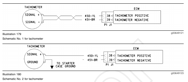
If the vehicle tachometer is driven by the ECM the vehicle tachometer will be connected to the ECM through connector J1/P1:38 and/or J1/P1:39. Some tachometers require only one of the ECM tachometer signal lines to operate while other tachometers may require both of the ECM tachometer signal lines to operate.
The following background information is related to this procedure:
The tachometer circuit consists of the tachometer that is connected to the ECM through connector J1/P1 and associated wiring. The ECM engine speed signal is provided by the primary engine speed/timing sensor. The ECM converts the signal from the primary engine speed/timing sensor into engine rpm in pulses per revolution before the ECM sends a signal to the tachometer. The selection of the pulses per revolution for the tachometer is done through the “Tachometer Calibration” parameter.
The ECM tachometer signal is programmable from 12.0 to 500.0 pulses per revolution in 0.1 increments. The tachometer must be calibrated identically to this value for proper operation.
The most likely source of a tachometer circuit problem is the vehicle wiring. The second most likely source of a tachometer circuit problem is the tachometer and the least likely source of a tachometer circuit problem is the ECM.
Note: A tachometer may also be driven by the SAE J1587 data link or the J1939 data link. If the engine ECM communicates with the electronic service tool and the instrument cluster uses the signal from a data link, the problem is in one of two locations. Either the problem is in the wiring from the ECM to the dash, or the problem is in the dash.
Note: Do not disturb the secondary engine speed/timing sensor and the primary engine speed/timing sensor in order to troubleshoot a tachometer circuit problem. If there is a problem that is associated with the sensors, refer to Troubleshooting, “Engine Speed/Timing Sensor Circuit – Test”. Any problem that is associated with the secondary engine speed/timing sensor and the primary engine speed/timing sensor will be apparent because of engine operation with a diagnostic code that is present. There are no diagnostic codes that are associated with the tachometer circuit.
Test Step 1. Use an Electronic Service Tool to Check the ECM Tachometer Signal
A. Connect the electronic service tool at the data link connector.
B. Turn the key switch to the ON position.
C. Access the “Tachometer Circuit Test”. Access the following display screens in order:
• “Diagnostics”
• “Diagnostic Tests”
• “Special Test”
D. While the dash tachometer is being monitored, begin the test.
Expected Result:
RESULT 1 The dash tachometer indicates approximately 1500 ± 150 rpm and the dash tachometer is stable.
RESULT 2 The tachometer does not indicate an engine rpm or the tachometer is erratic.
RESULT 3 The tachometer rpm is stable but the tachometer rpm is not within 50 rpm of 1500 rpm.
Results:
• Result 1 – The ECM and the tachometer are OK.
STOP.
• Result 2 – The engine rpm is not indicated or the engine rpm is erratic. Proceed to Test Step 2.
• Result 3 – The engine rpm is not within 50 rpm of 1500 rpm. Proceed to Test Step 6.
Test Step 2. Determine the Type of Connection
A. Determine if the wiring for the tachometer is wired directly to the ECM or through the J1939 or J1587 data link.
Expected Result:
The tachometer is wired directly to the ECM.
Results:
• OK – The tachometer is wired directly to the ECM. Proceed to Test Step 3.
• J1939 data link – The tachometer is wired through the J1939 data link.
Repair: Refer to Troubleshooting, “Powertrain
Data Link Circuit – Test”.
STOP.
• J1587 data link – The tachometer is wired through the J1587 data link.
Repair: Refer to Troubleshooting, “ATA (SAE J1587 / J1708) Data Link Circuit – Test”.
STOP.
Test Step 3. Inspect Electrical Connectors and Wiring
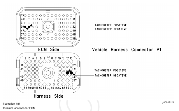
A. Thoroughly inspect the J1/P1 ECM connector, the firewall bulkhead connector, and the terminals for the tachometer in the connectors. Refer to Troubleshooting, “Electrical Connectors – Inspect” for details.
B. Perform a 45 N (10 lb) pull test on each of the wires in the ECM connector that are associated with the terminals for the tachometer:
• P1:38
• P1:39
Refer to Illustration 181.
C. Check the ECM connector (allen head screw) for the proper torque of 6.0 N·m (55 lb in).
D. Check the harness and wiring for abrasion and pinch points from the battery to the ECM.
Expected Result:
All connectors, pins and sockets should be completely coupled and/or inserted and the harness and wiring should be free of corrosion, abrasion or pinch points.
Results:
• OK – Proceed to Test Step 4.
• Not OK
Repair: Perform the following repair:
1. Repair the connectors or wiring and/or replace the connectors or wiring. Ensure that all of the seals are properly in place and ensure that the connectors are completely coupled.
2. Verify that the repair eliminates the problem.
STOP.
Test Step 4. Check the ECM Connection to the Tachometer
A. Inspect the J1/P1 ECM connector. Verify that the connections are present at P1:39 Tachometer? and/or P1:38 Tachometer+.
Note: Some of the tachometers require only one signal line to be connected. Either of the ECM terminals can be used for this type of tachometer. The other wire should be left disconnected. If both wires are connected, and one indicates an open circuit, repair this line.
Expected Result:
Wires are connected to the ECM terminals for the tachometer, P1:39 (Tachometer?) and/or P1: 38 (Tachometer+).
Results:
• OK – The ECM is providing the signal for the tachometer. Proceed to Test Step 5.
• Not OK – The ECM is not connected in order to supply the signal to the tachometer.
Repair: Send the vehicle to the OEM dealer in order to repair the tachometer circuit.
STOP.
Test Step 5. Check the ECM Tachometer Signal
Note: Performing certain steps within this procedure requires the use of a multimeter that is capable of
measuring a PWM Duty Cycle.
A. Disconnect the J1/P1 ECM connector.
B. Connect a 140-2266 Cable (Seventy-Pin Breakout) between the J1 and P1 ECM connector.
C. Fabricate two jumper wires 100 mm (4 inch) long.
Crimp a Deutsch Pin to one end of each wire.
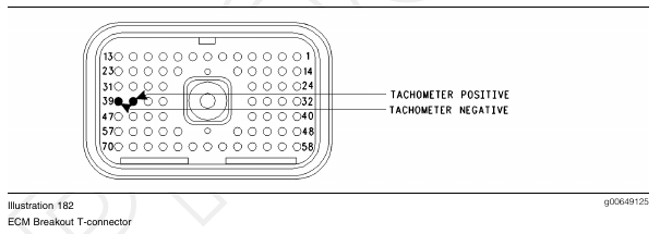
D. Insert one of the jumper wires into P1:39 (Tachometer?) of the breakout T and insert the other jumper wire into P1:38 (Tachometer+) of the breakout T.
Refer to Illustration 182.
E. Access the “Tachometer Circuit Test”. Access the following display screens in order:
• “Diagnostics”
• “Diagnostic Tests”
• “Special Test”
F. Attach one of the multimeter leads to the jumper wire from P1:38.
G. Attach the other multimeter lead to the jumper wire from P1:39.
H. While the “Tachometer Circuit Test” is being run, observe the reading on the multimeter.
Expected Result:
The multimeter indicates a duty cycle from 30 to 70 percent from each of the terminals for the tachometer while the engine is running.
Results:
• OK – The ECM tachometer output is OK.
Repair: Remove the breakout T and reconnect the J1/P1 ECM connector.
Proceed to Test Step 7.
• Not OK – The duty cycle is out of the range.
Repair: Perform the following repair:
1. Temporarily connect a test ECM.
2. Remove all jumpers and replace all connectors.
3. Recheck the system for active diagnostic codes.
4. Repeat the test step.
5. If the problem is resolved with the test ECM, reconnect the suspect ECM.
6. If the problem returns with the suspect ECM, replace the ECM.
7. Verify that the repair eliminates the problem.
STOP.
Test Step 6. Inspect the Tachometer Calibration
A. Determine the tachometer engine speed calibration setting in pulses per revolution. You may be required to contact the OEM dealer or you may be required to send the vehicle to the OEM dealer for this information.
B. Connect the electronic service tool to the data link connector.
C. Check the “Tachometer Calibration” parameter on the “Configuration” screen.
Expected Result:
The “Tachometer Calibration” matches the ECM tachometer calibration.
Results:
• OK – The tachometer is correctly calibrated.
Repair: Perform the following repair:
1. If the tachometer is correctly calibrated but the tachometer does not work, replace the tachometer or send the tachometer to the OEM dealer for repair.
2. Verify that the repair eliminates the problem.
STOP.
• Not OK – The tachometer is not correctly calibrated.
Repair: Perform the following repair:
1. Calibrate the tachometer in order to match the ECM.
a. If the tachometer calibration is known and the tachometer calibration is within 12.0 to 500.0 pulses per revolution, change the Customer Programmable Parameter of the ECM “Tachometer Calibration” in order to match the tachometer.
2. Verify that the repair eliminates the problem.
STOP.
Test Step 7. Check the ECM Connection to the Tachometer
A. Find the tachometer signal connections to the tachometer.
B. Disconnect the wires from the ECM to the tachometer at the ECM connector and at the tachometer.
Refer to Illustration 182.
C. Check for continuity through the wires to the ECM connector P1:39 (Tachometer?) and P1:38 (Tachometer+).
Note: Some of the tachometers require only one signal line to be connected. Either of the ECM terminals can be used for this type of tachometer.
The other wire should be left disconnected. If both wires are connected, and one indicates an open circuit, repair this line.
Expected Result:
The wires from the ECM to the tachometer are undamaged.
Results:
• OK – The wiring is OK. Proceed to Test Step 8.
• Not OK – The wiring is damaged.
Repair: Perform the following repair:
Either repair the wiring or send the vehicle to the OEM dealer. Verify that the repair eliminates the problem.
STOP.
Test Step 8. Check the Supply Voltage to the Tachometer
A. Connect the tachometer lines to the ECM and the tachometer.
B. Check the positive battery connections and the negative battery connections to the tachometer.
Include the fuses and the circuit protection.
Expected Result:
The tachometer is receiving the correct battery supply voltage.
Results:
• OK – The battery supply voltage is OK.
Repair: Perform the following repair:
If the tachometer is receiving the correct battery supply voltage but the tachometer does not work, replace the tachometer or send the tachometer to the OEM dealer for repair.
STOP.
• Not OK – The battery supply voltage is incorrect.
Repair: Perform the following repair:
1. Repair the wiring for the battery connection.
2. Verify that the repair eliminates the problem.
STOP.