Batteries can emit explosive gases. To reduce the possibility of personal injury, always ventilate the compartment before servicing the batteries. To reduce the possibility of arcing, remove the negative (-) battery cable first and attach the negative (-) battery cable last.
CAUTION
Place a wooden block, the width of the oil pan, between the floor jack and oil pan to prevent damage to the engine.
Remove the transmission, clutch, and all related components, if equipped. Consult the manufacturer’s instructions.
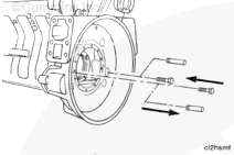
Remove the flywheel. Refer to Procedure to 016-005.
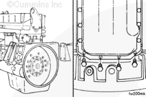
Use a floor jack or a suitable lifting fixture to support the rear of the engine.
Disconnect the battery cables.
Remove the starting motor. Refer to Procedure 013-020.
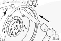
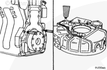
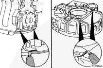
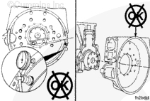
Loosen six capscrews on each side of the oil pan at the end closest to the flywheel housing. This will allow enough clearance to remove the flywheel housing.
Be careful not to tear the oil pan gasket. If the oil pan gasket is damaged, the oil pan must be removed and the gasket replaced.
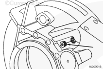
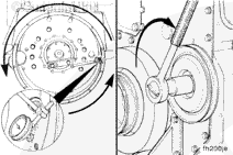
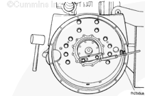
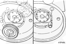
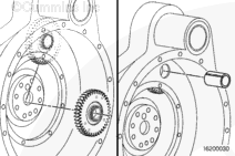
Check the output shaft rolling resistance with a torque wrench.
The rolling resistance must be between 0.6 to 1.1 N•m [5 to 10 in-lb].
If the resistance does not meet these specifications, add or subtract shims to obtain the correct rolling resistance. Refer to the L10, Engine Shop Manual: Bulletin 3810476
NOTE: Adding shims will increase resistance; removing shims will decrease resistance. Any combination of shims can be used.
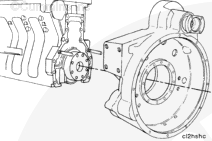
Do not damage the oil pan gasket when installing the flywheel housing.
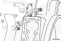
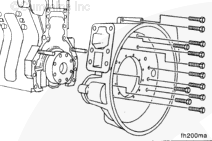
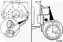
The flywheel housing bore must be aligned with the crankshaft. Do not tighten the capscrews to the final torque value until the flywheel housing is aligned.
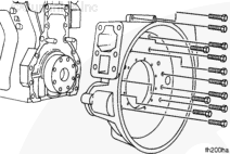
Install the capscrews. Remove the guide pins, and install the remaining two capscrews.
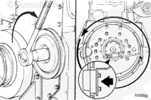
If the maximum bore alignment does not meet the specifications, use a rubber hammer to move the housing in the necessary direction and repeat the measurement procedure.
If the bore alignment will not meet the specifications or the bore is not round, the housing must be replaced.
If bore and face alignment does not meet the specifications, loosen the housing capscrews. Tighten the capscrews and measure the bore and face alignment again.
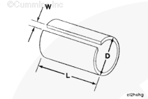
Manufacture a sleeve from 38.1 mm outside diameter (O.D). [1.50 in O.D.] (D) PVC, aluminum, thin wall hose, or equivalent, to the following dimensions:
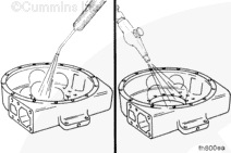
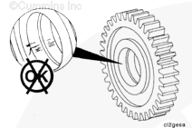
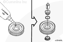
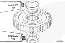
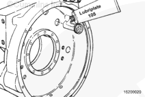
Apply Lubriplate™ 105 multi-purpose lubricant , or equivalent, on the outer races and the bearings.
NOTE: The outer bearing races of new replacement gears are already pressed into the gear.
Install the bearing and spacer into the idler gear. Use the manufactured sleeve to hold the bearing assembly together when installing the idler gear assembly.
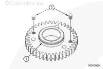
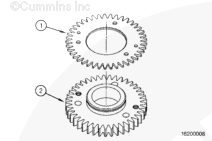
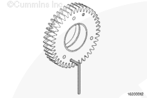
Insert the large spacer ring into the bore of the thicker gear. Press it in until the ring snaps into the groove that has been machined into the center of the bore.
The outer bearing races of new replacement gears are already pressed into the gear. Excessive grease in the housing insert or on the shaft can create a hydraulic lock. Use moderation when applying lubrication.
With the larger diameter of the tapered race facing out, press each bearing race into the bore until it stops against the spacer ring.
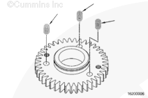
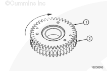
Position the spacers 180 degrees apart on top of the thin gear. Leave enough room between the spacers and the hub of the thick gear so that the snap ring can be installed over the hub.
Using a press, compress the spacers until the thin gear has been pushed tight against the thick gear.
Install a snap ring over the hub of the thick gear. If the snap ring interferes with the spacers, release the press and move the spacers out from the center of the bore. Repeat the preceding step.
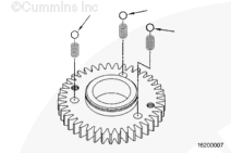
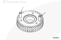
Turn the set screws until they are extended into the coned holes of the thin gear. Make sure that the teeth of the thin gear and the thick gear align when the set screws stop. The set screws are in the holes that are 180 degrees apart.
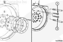
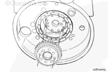
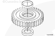
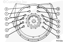
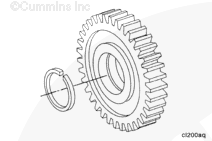
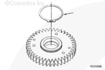
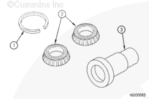
The small spacer ring (1), roller bearings (2), idler shaft (3), and the races that have already been installed on the thick gear, comprise a matched set. The gear and bearing hardware must be kept together until it is installed in the REPTO housing.
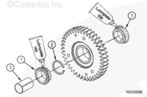
The outer bearing races of new replacement gears are already pressed into the gear. Excessive grease in the housing insert or on the shaft can create a hydraulic lock. Use moderation when applying lubrication.
Apply Lubriplate™ 105 multi-purpose lubricant or equivalent, to the outer races and the bearings.
Install the bearings (1) and spacer (2) into the backlash gears. Use the fabricated sleeve (3) to hold the bearing assembly together until it has been inserted into the REPTO housing.
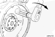
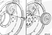
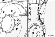
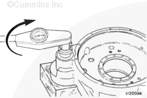
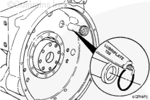
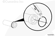
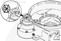
Apply Lubriplate® 105 multi-purpose lubricant under the head of the idler shaft capscrew. Insert the capscrew through the idler shaft. Tighten the installation capscrew with a torque wrench.
NOTE: The torque needed to draw the idler shaft in place must not exceed 88 N•m [65 ft-lb]. If installation torque exceeds this amount, it indicates misalignment between the bore and the shaft. Remove the idler shaft and install it again.
Do not use a hammer when installing the idler shaft and capscrew. The part can be damaged.
After the idler shaft has been seated, remove the capscrew.
Apply pipe sealant to the threads of the idler shaft capscrew. Apply Lubriplate™ 105 multi-purpose lubricant under the head of the capscrew. Install the capscrew and tighten to its final torque value.
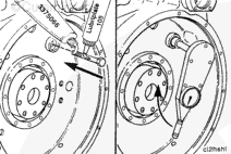
These two set screws must be completely retracted into the thick gear so that the anti-backlash system will operate properly. If they protrude out of the thick gear, the anti-backlash system will be damaged.
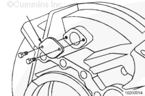
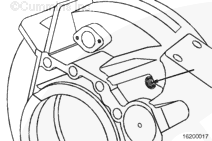
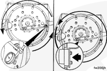
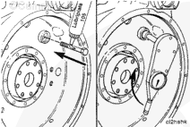
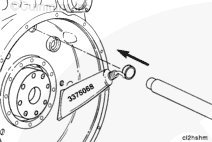
Use a 7/32 inch Allen wrench to back the set screw away from the thin gear.
Rotate the engine crankshaft until the other set screw is accessible.
Back the set screw away from the thin gear.
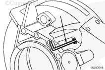
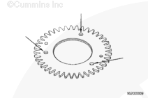
Inspect the gears to make sure that the backlash has been activated.
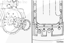
Turn the output flange so that the flat sides are on the top and bottom. This prevents any interference when the transmission is installed onto the housing.
Batteries can emit explosive gases. To reduce the possibility of personal injury, always ventilate the compartment before servicing the batteries. To reduce the possibility of arcing, remove the negative (-) battery cable first and attach the negative (-) battery cable last.
CAUTION
Place a wooden block, the width of the oil pan, between the floor jack and oil pan to prevent damage to the engine.
Install the starting motor. Refer to Procedure 013-020.
Install the battery cables.
Use a floor jack or a suitable lifting fixture to support the rear of the engine.
Install the flywheel. Refer to Procedure to 016-005.
Install the transmission, clutch, and all related components, if equipped. Consult the manufacturer’s instructions.
Hello, I'm Jack, a diesel engine fan and a blogger. I write about how to fix and improve diesel engines, from cars to trucks to generators. I also review the newest models and innovations in the diesel market. If you are interested in learning more about diesel engines, check out my blog and leave your feedback.
View all posts by Jack
 WARNING
  CAUTION


;)
;)
;)
;)
;)
;)
;)
;)
;)
;)
;)
;)
;)
;)
;)
;)
;)
;)
;)
;)
;)
;)
;)
;)
;)
;)
;)
;)
;)
;)
;)
;)
;)
;)
;)
;)
;)
;)
;)
;)
;)
;)
;)
;)
;)
;)
;)
;)
;)
;)
;)
;)
;)
;)
;)
;)
;)
;)
;)
;)
;)
;)
;)
;)
;)
;)
;)
;)
;)
;)
;)
;)
;)
;)
;)
;)
;)
;)
;)
;)
;)
;)
;)
;)
;)
;)
;)
;)
;)
;)
;)
;)
;)
;)
;)
;)
;)
;)
;)
;)
;)
;)
;)
;)
;)
;)
;)
;)
;)
;)
;)
;)
;)
;)
;)
;)
;)
;)