NOTE: Due to the number of engines and applications, this procedure has been written to be generic. Illustrations within this procedure will not represent all engines and applications.
NOTE: Make sure the dynamometer capacity is sufficient to permit testing at 100 percent of the engine’s rated horsepower. If the capacity is not enough, the testing procedure must be modified to the restrictions of the dynamometer.
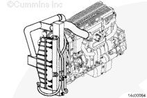
Use engine lifting fixture, Part Number 3162871, to install the engine test stand. Align and connect the dynamometer. Refer to the manufacturer’s instructions for aligning and testing the engine.
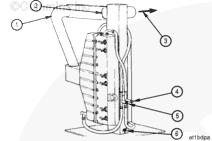
The use of a remote aftercooler is mandatory whenever a Cummins® charge-air cooled engine is attached to an engine dynamometer for the purpose of engine run-in, performance testing, and/or engine diagnostics. Do not attempt to run a Cummins® charge-air cooled engine without a means of controlling the intake manifold air temperature. Dynamometer-room charge-air cooler, Part Number 3823978, utilizes twin Big Cam™ III aftercooler assemblies arranged for parallel air and water flow to cool the intake air to acceptable levels.
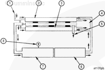
The parallel airflow circuit heat exchangers provide optimum performance by delivering air to the mixer at temperatures no higher than 66°C [151°F] and with less than the maximum allowable intake air pressure drop. The remote aftercooler removes energy from the intake air compressed and heated by the turbocharger to temperatures as high as 210°C [410°F] and then cooled to temperatures of 66°C [151°F] using city water at 16°C [61°F].
Water from a city tap line flows to the aftercooler through a 25.4 mm [1-inch] inner diameter neoprene hose. Testing has shown that 45.4 liter [12 gal] per minute city water flow is required (22.7 liter [6 gal] per minute per aftercooler core) to adequately cool the intake air for the 435 through 500 horsepower-rated engines. A typical garden hose is not suitable for this flow, due to the excessive restriction. A low-restriction ball-type or gate valve is suitable for the operation, provided that the required flow rates are achieved.
Water returns to the drain or reservoir from the aftercoolers through a 25.4 mm [1-inch] inner diameter hose. A low-restriction gate valve or ball valve must be placed on the drain line(s) to regulate water flow through the aftercoolers. This provides the ability to maintain optimum intake air temperature during the test or run-in procedure.
The condensate that will develop as the intake air is cooled in the remote aftercooler is allowed to drain at all times through a hole at the bottom of the tubular steel manifold between the aftercoolers. This fitting must remain unobstructed throughout each use of the aftercoolers.
NOTE: Some air will escape through the condensate drain opening, but it is insignificant compared to the total airflow.
The airflow piping requires a 101.6 mm [4 in] inner diameter aluminum steel piping. The flow circuit must have as few bends as possible, maximizing the length of straight sections. However, when bends are required, use long elbows. Do not use square elbows or anything that changes the airflow direction quickly. To reduce intake air restriction, airflow direction changes must occur gradually.
NOTE: All air compressors manufactured by Cummins Inc. must operate during the engine run-in. During the performance check, all air compressors must be in the unloaded or non-operating mode.
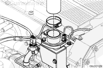
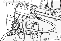
Connect a source of compressed air capable of producing 665 kPa [96 psi] to the air compressor unloader (1). This air line must contain a valve between the air source and the unloader.
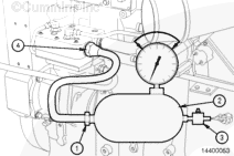
NOTE: The compressed air load in the accompanying illustration must be attached to the air compressor outlet (2).
Use an air tank (2). Install an air regulator (3) capable of maintaining 345 to 517 kPa [50 to 75 psi] of air pressure at both minimum and maximum engine rpm.
Install a steel tube or high temperature hose (1).
Hose Temperature
celsius
fahrenheit
235
MIN
500
Connect the tube or hose (1) to the air compressor outlet.
Inspect the voltage rating on the starting motor before installing the electrical wiring.
WARNING
Batteries can emit explosive gases. To reduce the possibility of personal injury, always ventilate the compartment before servicing the batteries. To reduce the possibility of arcing, remove the negative (-) battery cable first and attach the negative (-) battery cable last.
Install the electrical wiring to the starting motor and batteries, if used.
If another method of starting the engine is used, follow the manufacturer’s instructions to make the necessary connections.
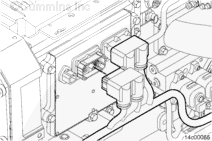
Engines operating on an engine dynamometer require the engine harness be installed and connected to the engine. Additionally, the engine controller harness, Part Number 3164242, and engine controller, Part Number 3163890, must be used to properly control the engine during the dynamometer run.
Connect the engine controller harness Deutsch™ connector to the ECM OEM port.
Batteries can emit explosive gases. To reduce the possibility of personal injury, always ventilate the compartment before servicing the batteries. To reduce the possibility of arcing, remove the negative (-) battery cable first and attach the negative (-) battery cable last.
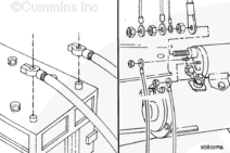
Connect the dynamometer test OEM wiring harness starter solenoid lead (yellow) to the starter solenoid. Connect the ground lead (black) to the starter or battery negative (-) or ground side. Connect the +12-VDC power lead (red) to either the starter or battery positive (+12-VDC) side.
To monitor engine performance correctly, record the following parameters. To limit dynamometer operating time, instrument the engine or use INSITE™ electronic service tool to make as many checks as possible.
Intake Manifold Air Temperature Control – Chassis Dynamometer test
When operating an engine on a chassis dynamometer, lock the cooling fan in the ON position for best results.
If the unit does not have a manual fan switch, use INSITE™ electronic service tool/Set Up for Dynamometer feature to lock the fan in the ON position. Refer to Procedure 014-008 in Section 14.
Use INSITE™ electronic service tool to monitor the intake manifold air temperature.
Observe and record the intake manifold air temperature.
The intake manifold air temperature must not exceed the maximum allowable temperature. See the Specifications – Engine Testing page in this section for the maximum allowable intake manifold air temperature. The engine protection system will disrupt performance if the temperature exceeds this level. Maintain the intake manifold air temperature below the maximum allowable temperature during chassis dynamometer operation.
If the intake manifold air temperature exceeds the maximum allowable temperature during the test, unload the dynamometer and allow the engine to cool.
Shut the engine off and inspect the charge air cooler fins for obstructions to the airflow.
Check the fan drive. Make sure the fan is locked in the ON position.
Remove any obstructions, such as a winterfront or debris. Manually lock the shutters in the OPEN position, if equipped.
Inspect the dynamometer room for an adequate supply of suitably cool or outside air. Make sure that dynamometer room air recirculation is not an issue.
Use blowby checking tool, Part Number 3822566 (ISM) or Part Number 3822567 (ISX), and water manometer, Part Number ST-1111-3, to measure the engine crankcase pressure.
Install the blowby checking tool to the end of the blowby tube. Install the water manometer to the blowby checking tool. Operate the engine at advertised horsepower rpm at full load. Observe and record the blowby.
If the coolant temperature exceeds the maximum allowable coolant temperature, unload the dynamometer and allow the engine to cool.
Shut the engine off and inspect the radiator fins for obstructions to the airflow.
Check the fan drive. Make sure the fan is locked in the ON position.
Remove any obstructions, such as a winterfront or debris. Manually lock the shutters in the OPEN position, if equipped.
Inspect the dynamometer room for an adequate supply of suitable cool or outside air. Make sure that dynamometer room air recirculation is not an issue.
Use immersion probe, Part Number 3824965, with a digital multimeter, Part Number 3377161, and a thermocouple module, Part Number 3824963, to monitor fuel temperature.
Hello, I'm Jack, a diesel engine fan and a blogger. I write about how to fix and improve diesel engines, from cars to trucks to generators. I also review the newest models and innovations in the diesel market. If you are interested in learning more about diesel engines, check out my blog and leave your feedback.
View all posts by Jack


 WARNING


;)
;)
;)
;)
;)
;)
;)
;)
;)
;)
;)
;)
;)
;)
;)
;)
;)
;)
;)
;)
;)
;)
;)
;)
;)
;)
;)
;)
;)
;)
;)
;)
;)
;)
;)
;)