To reduce the possibility of engine damage, the upper and lower bearings must be installed in the correct location. The upper bearing has an oil groove. The bearing shells are marked with the words “upper” and “lower” for identification.
CAUTION
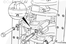
To correctly position the bearing and prevent engine damage, the bearing tang (1) must e in the slot (2) of the bearing saddle.
CAUTION
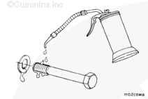
Only use Loctite™ 518 anaerobic sealant on the main cap joint mating surface. Other sealants can become hard, brittle, and allow oil and debris into the main bearing/block joint.
CAUTION
The bead must be 3 to 5 mm [0.12 to 0.2 in] wide and must not enter the main bearing shell inside diameter. Sealant in the main bearing can cause engine damage.
Low oil pressure faults can occur if more than one set undersize main bearings are installed in the same engine.
NOTE: Both upper and lower undersize main bearing shells must be installed as a set in the same block location.
Undersize main bearing installation procedures are the same as standard main bearings procedures. Both upper and lower undersized main bearing shells must be installed as a set in the same block location.
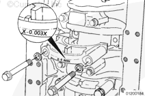
For undersize main bearing installation, mark the outside back of the main cap X -0.003 X with a permanent white Dykem™ marker to identify bearing location for future repairs. Allow the Dykem™ to dry before oil is added.
The bead must be 3 to 5 mm [0.12 to 0.2 in] wide and must not enter the main bearing shell inside diameter. Sealant in the main bearing can cause engine damage.
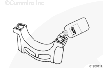
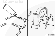
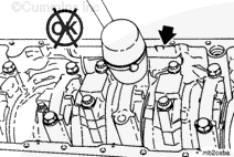
Locate the leading edge of the main bearing cap clearance chamfer.
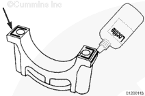
Apply a bead of Loctite™ 518 anaerobic sealant to the leading edge of the main bearing cap clearance chamfer (as shown).
Repeat this procedure on the opposite side of the main bearing cap.
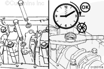
To reduce the possibility of bore size issues, clearance issues, or both, the main bearing capscrews must be tightened within 15 minutes of the Loctite™ 518 anaerobic sealant application.
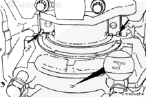
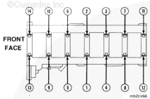
The main bearing caps are numbered 1 through 7 from front to rear in the cylinder block. The caps must be installed so the number on the cap matches the bearing saddle in the block. The lock tangs in the main bearing saddle and bearing cap must be on the same side.
Make sure the proper main cap capscrew torque procedure is used when torquing main bearings. The use of the improper torque procedure will damage the engine.
Tighten all older blocks (prior to Engine Serial Number (ESN) 35011095) main bearing capscrews in alternating sequence to the following torque values:
Torque Value:
68 n.m
[50 ft-lb]
Loosen completely
68 n.m
[50 ft-lb]
Rotate 180 degrees
All torque-to-yield blocks (ESN first 35011095) or blocks with TTY stamped on the rear engine serial number stamp pad must be tightened in alternating sequence to the following torque values:
Hello, I'm Jack, a diesel engine fan and a blogger. I write about how to fix and improve diesel engines, from cars to trucks to generators. I also review the newest models and innovations in the diesel market. If you are interested in learning more about diesel engines, check out my blog and leave your feedback.
View all posts by Jack
 CAUTION
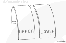


;)
;)
;)
;)
;)
;)
;)
;)
;)
;)
;)
;)
;)
;)
;)
;)
;)
;)
;)
;)
;)
;)
;)
;)
;)
;)
;)
;)