Engine Performance Troubleshooting Tree – ISM with CM876

Symptoms
- Engine Acceleration or Response Poor
- Cranking Fuel Pressure is Low
- Engine Operating Fuel Pressure is Low
- Engine Difficult to Start or Will
Not Start (Exhaust Smoke) - Engine Difficult to Start or Will
Not Start (No Exhaust Smoke) - Engine Power Output Low
- Engine Runs Rough at Idle
- Engine Runs Rough or Misfires
- Engine Speed Surges at Low or High Idle
- Engine Speed Surges Under Load or in Operating Range
- Smoke, Black – Excessive
- Smoke, White – Excessive
- Engine Shuts Off or Dies Unexpectedly or Dies During Deceleration
- Engine Starts But Will
Not Keep Running - Engine Will
Not Reach Rated Speed (RPM)
How To Use This Tree
This symptom tree can be used to troubleshoot all performance based symptoms listed above. Start by performing Step 1 troubleshooting. Step 2 will ask a series of questions and will provide a list of troubleshooting steps to perform depending on the symptom.
Shop Talk
Verify the electronic control module (ECM) calibration is correct. Check the calibration revision history found on QuickServe™ Online for applicable fixes to the calibration stored in the ECM. If necessary, calibrate the ECM.
Refer to Procedure 019-032 in Section 19.
Troubleshooting Steps
| STEPS | SPECIFICATIONS | |
|---|---|---|
| STEP 1. | Perform basic troubleshooting procedures. | |
| STEP 1A. Check for active fault codes or high counts of inactive fault codes. | Active fault codes or high counts of inactive fault codes? | |
| STEP 1B. Perform basic troubleshooting checks. | All steps have been verified to be correct? | |
| STEP 1C. Perform INSITE™ electronic service tool Monitor Test. | Is ‘Engine Operating State’ reading a value that can cause an engine derate? | |
| STEP 2. | Determination of engine symptom. | |
| STEP 2A. Low power, poor acceleration, or poor response. | Is the engine symptom low power, poor acceleration, or poor response? | |
| STEP 2B. Engine runs rough or misfires. | Is the engine symptom Engine Runs Rough or Misfires? | |
| STEP 2C. Excessive black smoke. | Is the engine symptom Excessive Black Smoke? | |
| STEP 2D. Excessive white smoke. | Is the engine symptom Excessive White Smoke and the engine is using coolant? | |
| STEP 2D-1. Excessive white smoke. | ||
| STEP 2E. Engine speed surge or engine speed unstable. | Is the engine symptom Engine Speed Surge or Engine Speed Unstable? | |
| STEP 2F. Engine will not start or difficult to start, engine shuts off unexpectedly. | Is the symptom Engine Difficult to Start or Will Not Start, or Engine Shuts Off Unexpectedly? | |
| STEP 2G. Engine run on, or will not shut down. | Is the engine symptom Engine Run On or Slow to Shut Down after operated at high idle for 1 minute then keyed OFF? | |
| STEP 3. | No-start troubleshooting procedures. | |
| STEP 3A. Check fuel shutoff valve voltage. | Is the fuel shutoff valve voltage greater than 11-VDC? | |
| STEP 3A-1. Check ECM keyswitch voltage. | ||
| STEP 3A-2. Check the fuel shutoff valve wire. | ||
| STEP 3B. Check fuel shutoff valve resistance. | Is the fuel shutoff solenoid resistance 1 to 5 ohms for 6-VDC solenoids, 6 to 15 ohms for 12-VDC solenoids, 24 to 50 ohms for 24-VDC solenoids, 42 to 80 ohms for 32-VDC solenoids, 46 to 87 ohms for 36-VDC solenoids, 92 to 145 ohms for 48-VDC solenoids, 315 to 375 ohms for 74-VDC solenoids, 645 to 735 ohms for 115-VAC solenoids? |
|
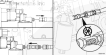
| STEP 3C. Check fuel shutoff valve actuator disk. | Debris or damage found on the valve disc, valve seat, or actuator disc? | |
| STEP 3D. Check for an engine equipped with a priming pump. | Does the engine use a priming pump? | |
| STEP 3D-1. Check for correct priming pump operation. | ||
| STEP 3D-2. Check priming pump pressure. | ||
| STEP 3E. Check for coolant in the EGR transfer tube. | Is coolant present in the crossover tube? | |
| STEP 4. | Fuel system checks. | |
| STEP 4A. Check for air in the fuel. | Air bubbles visible in the sight glass? | |
| STEP 4B. Check fuel inlet restriction. | Is fuel inlet restriction less than the specifications? | |
| STEP 4C. Check drain line restriction. | Is fuel drain line restriction less than 89 mm-Hg [3.5 in-Hg]? | |
| STEP 4D. Check pump output pressure. | Does the fuel pressure meet the specification? | |
| STEP 4E. Check fuel gear pump check valve. | Is check valve installed and operating correctly? | |
| STEP 4F. Check fuel supply line for restrictions. | Are fuel lines free from restrictions? | |
| STEP 4G. Check for plugged fuel drillings in the cylinder head. | Has plastic insert been removed from the fuel supply passage in the cylinder head? | |
| STEP 5. | Injector diagnostics. | |
| STEP 5A. Perform INSITE™ electronic service tool cylinder cutout test. | Do all cylinders pass the cylinder cutout test? | |
| STEP 6. | Air handling diagnostic checks. | |
| STEP 6A. Start engine and read fault codes. | Active fault codes? | |
| STEP 6B. Inspect the turbocharger blades for damage. | Damage found on turbocharger fins? | |
| STEP 7. | Check EGR system for proper operation. | |
| STEP 7A. Check for EGR related fault codes. | EGR related fault codes present? | |
| STEP 7B. Check for inactive EGR Differential Pressure Sensor fault codes. | Fault Code 1866, 2273, or 2274 active? | |
| STEP 7C. Check the EGR differential pressure tubes for leaks. | Leaks detected at either the low or high EGR differential pressure tubes? | |
| STEP 7D. Check the EGR differential pressure sensor adapter for leaks. | Leaks detected at the EGR differential pressure sensor adapter? | |
| STEP 7E. Check the EGR differential pressure tubes for plugging. | Debris or soot found in either EGR differential pressure tube? | |
| STEP 7F. Check for air leaks in the EGR system. | Air leaks found in the EGR connection tubing? | |
| STEP 8. | Verify electronic features are operating correctly. | |
| STEP 8A. Verify accelerator pedal travel. | Does the Percent Accelerator read 0 when the accelerator is released and 100 percent when the accelerator is depressed? | |
| STEP 8B. Monitor vehicle speed. | Does the vehicle speed read 0 when the vehicle is not moving? | |
| STEP 8C. Verify electronic feature settings are correct. | Are the electronic features set correctly? | |
| STEP 8D. Check ambient air pressure sensor reading. | Is the barometric pressure sensor reading in INSITE™ electronic service tool within 5 percent of the present local barometric pressure reading? | |
| STEP 8E. Check the intake manifold pressure sensor accuracy. | INSITE™ electronic service tool reading within 17 kPa [2.5 psi] of mechanical gauge reading? | |
| STEP 9. | Perform base engine mechanical checks. | |
| STEP 9A. Verify overhead adjustments are correct. | Are the overhead settings within the reset limits? | |
| STEP 9B. Verify engine brake adjustment. | Are the engine brake settings within the reset limits? | |
| STEP 9C. Check air intake restriction. | Is air intake restriction greater than 635 mm-H 20 [25 in-H 20] for a used air filter or 254 mm-H 20 [10 in-H 20); for a new filter? |
|
| STEP 9D. Check exhaust restriction. | Is exhaust restriction greater than 304.8 mm-Hg [12.0 in-Hg]? | |
| STEP 9E. Inspect the charge-air cooler. | Is the pressure drop 34 kPa [5 psi] or less in 15 seconds? | |
| STEP 9F. Verify engine blowby is within specification. | Are the engine blowby measurements within specification? | |
| STEP 9F-1. Verify turbocharger contribution to engine blowby. | ||
| STEP 10. | Aftertreatment Checks | |
| STEP 10A. Check for aftertreatment related fault codes. | Fault codes related to the aftertreatment system are found to be active? | |
| STEP 10B. Perform basic aftertreatment troubleshooting checks. | All parts have been visually inspected, and appear to be functioning properly? | |
| STEP 10C. Check for signs of internal damage to the aftertreatment system. | Any visible smoke (black or white) is present during the snap throttle acceleration? | |
| STEP 10D. Check exhaust restriction. | Is exhaust restriction greater than 304.8 mm-Hg [12.0 in-Hg]? | |
Guided Step 1 – Perform basic troubleshooting procedures.
| Guided Step 1A – Check for active fault codes or high counts of inactive fault codes. | |
|---|---|
Conditions
ActionCheck for active fault codes.
|
|
|
Active fault codes or high counts of inactive fault codes? |
|
| YES | NO |
| No Repair | No Repair |
|
Go to appropriate fault code troubleshooting tree
|
|
| Guided Step 1B – Perform basic troubleshooting checks. | |
|---|---|
ConditionsNone. ActionThe following items must be checked or verified before continuing:
|
|
|
All steps have been verified to be correct? |
|
| YES | NO |
| No Repair |
Correct the condition and verify complaint is no longer present after repair. |
|
Repair complete
|
|
| Guided Step 1C – Perform INSITE™ electronic service tool Monitor Test. | |
|---|---|
Conditions
ActionUse INSITE™ electronic service tool to monitor the parameter ‘Engine Operating State’ at the same engine operating conditions where the symptom occurs. Refer to Advanced Engine Performance Troubleshooting Techniques, Bulletin |
|
|
Is ‘Engine Operating State’ reading a value that can cause an engine derate? |
|
| YES | NO |
|
Determine if the engine derate is being caused by normal engine operation or by actual engine damage. Continue following troubleshooting steps as outlined in step 2 if engine damage is suspected. |
No Repair |
Guided Step 2 – Determination of engine symptom.
| Guided Step 2A – Low power, poor acceleration, or poor response. | |
|---|---|
ConditionsNone. ActionInterview the driver and verify the complaint. |
|
|
Is the engine symptom low power, poor acceleration, or poor response? |
|
| YES | NO |
|
Perform the troubleshooting steps in the recommended order listed below:
|
No Repair |
|
Perform the troubleshooting steps suggested in the repair procedure
|
|
| Guided Step 2B – Engine runs rough or misfires. | |
|---|---|
ConditionsNone. ActionInterview the driver and verify the complaint. |
|
|
Is the engine symptom Engine Runs Rough or Misfires? |
|
| YES | NO |
|
Perform the troubleshooting steps in the recommended order listed below:
|
No Repair |
|
Perform the troubleshooting steps suggested in the repair procedure
|
|
| Guided Step 2C – Excessive black smoke. | |
|---|---|
ConditionsNone. ActionInterview the driver and verify the complaint. Progressive damage to the aftertreatment system has occurred if black smoke is visible. Remove the exhaust aftertreatment system from the vehicle and inspect for reuse. Use the following procedure in the ISM, ISMe, and QSM11 Engines, Service Manual, Bulletin 3666322. |
|
|
Is the engine symptom Excessive Black Smoke? |
|
| YES | NO |
|
Perform the troubleshooting steps in the recommended order listed below:
|
No Repair |
|
Perform the troubleshooting steps suggested in the repair procedure
|
|
| Guided Step 2D – Excessive white smoke. | |
|---|---|
ConditionsNone. ActionInterview the driver and verify the complaint. |
|
|
Is the engine symptom Excessive White Smoke and the engine is using coolant? |
|
| YES | NO |
|
Perform the troubleshooting steps in the recommended order listed below:
|
No Repair |
|
Perform the troubleshooting steps suggested in the repair procedure
|
|
| Guided Step 2D-1 – Excessive white smoke. | |
|---|---|
ConditionsNone. ActionInterview the driver and verify the complaint. |
|
|
Is the engine symptom Excessive White Smoke and the engine is |
|
| YES | NO |
|
Perform the troubleshooting steps in the recommended order listed below:
|
No Repair |
|
Perform the troubleshooting steps suggested in the repair procedure
|
|
| Guided Step 2E – Engine speed surge or engine speed unstable. | |
|---|---|
ConditionsNone. ActionInterview the driver and verify the complaint. |
|
|
Is the engine symptom Engine Speed Surge or Engine Speed Unstable? |
|
| YES | NO |
|
Perform the troubleshooting steps in the recommended order listed below:
|
No Repair |
|
Perform the troubleshooting steps suggested in the repair procedure
|
|
| Guided Step 2F – Engine will not start or difficult to start, engine shuts off unexpectedly. | |
|---|---|
ConditionsNone. ActionInterview the driver and verify the complaint. |
|
|
Is the symptom Engine Will |
|
| YES | NO |
|
Perform the troubleshooting steps in the recommended order listed below:
|
No Repair |
|
Perform the troubleshooting steps suggested in the repair procedure
|
|
| Guided Step 2G – Engine run on, or will not shut down | |
|---|---|
ActionInterview the driver and verify the complaint. None |
|
|
Is the engine symptom Engine Run On or Slow to Shut Down after operated at high idle for 1 minute then keyed OFF? |
|
| YES | NO |
|
Perform the troubleshooting steps in the recommended order listed below: Step 5 – Injector Check Step 4 – Fuel System Checks Step 9 – Base Engine Checks |
No Repair |
|
Perform the troubleshooting steps suggested in the repair procedure.
|
Return to correct symptom trees.
|
Guided Step 3 – No-start troubleshooting procedures.
| Guided Step 3A – Check fuel shutoff valve voltage. | ||
|---|---|---|
Conditions
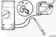
ActionMeasure the voltage from the fuel shutoff valve post to engine block ground. |
|
|
|
Is the fuel shutoff valve voltage greater than 11-VDC? |
||
| YES | NO | |
| No Repair | No Repair | |
| Guided Step 3A-1 – Check ECM Keyswitch Voltage | |
|---|---|
Conditions
ActionMeasure the voltage from the keyswitch input SIGNAL wire of the OEM harness to engine block ground. |
|
|
Is the keyswitch voltage equal to battery voltage? |
|
| YES | NO |
| No Repair |
Repair or replace the OEM power harness, keyswitch, or check the battery connections. Use the following procedure in the ISX CM871 and ISM CM876 Electronic Control Systems, Troubleshooting and Repair Manual, Bulletin 4021560. |
|
Repair complete
|
|
| Guided Step 3A-2 – Check the fuel shutoff valve wire. | ||
|---|---|---|
Conditions
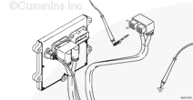
ActionMeasure the resistance from the fuel shutoff valve SIGNAL pin in the ECM connector to the fuel shutoff valve eyelet. |
|
|
|
Less than 10 ohms? |
||
| YES | NO | |
|
Call for pre-authorization to replace the ECM. Upon receipt of authorization, replace the ECM. Use the following procedure in the ISX CM871 and ISM CM876 Electronic Control Systems, Troubleshooting and Repair Manual, Bulletin 4021560. |
Repair or replace the engine harness. Use the following procedure in the ISX CM871 and ISM CM876 Electronic Control Systems, Troubleshooting and Repair Manual, Bulletin 4021560. |
|
|
Repair complete
|
||
| Guided Step 3B – Check fuel shutoff valve resistance | ||
|---|---|---|
Conditions
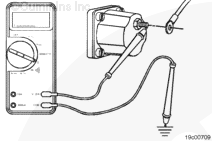
ActionMeasure the resistance from the fuel shutoff solenaoid post to engine block ground. The fuel shutoff solenoid must be between 20 – 25°C [68 – 77°F] before the use of the resistance specifications listed. |
|
|
|
Is the fuel shutoff solenoid resistance:
|
||
| YES | NO | |
| No Repair |
Replace the fuel shutoff solenoid. Use the following procedure in the ISX CM871 and ISM CM876 Electronic Control Systems, Troubleshooting and Repair Manual, Bulletin 4021560. |
|
| Guided Step 3C – Check fuel shutoff valve actuator disk | ||
|---|---|---|
Conditions
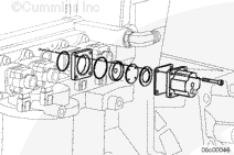
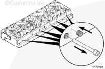
ActionCheck the valve disc, valve seat, and actuator disc for dirt, metal parts, bonding separation, corrosion, cracks, or wear. |
|
|
|
Debris or damage found on the valve disc, valve seat, or actuator disc? |
||
| YES | NO | |
|
Replace the damaged fuel shutoff valve component. Use the following procedure in the ISX CM871 and ISM CM876 Electronic Control Systems, Troubleshooting and Repair Manual, Bulletin 402156 |
No Repair | |
|
Repair complete
|
||
| Guided Step 3D – Check for an engine equipped with a priming pump. | |
|---|---|
Conditions
ActionListen for the lift pump operation. Listen for the priming pump operation after the keyswitch is turned to the ON position. If priming pump operation is not heard, inspect the unit to verify that is not equipped with a priming pump.
Not all ISM engines use a priming pump and |
|
|
Does the engine use a priming pump? |
|
| YES | NO |
| No Repair | No Repair |
| Guided Step 3D-1 – Check for correct priming pump operation. | |
|---|---|
Conditions
ActionListen for priming pump operation. Listen for the priming pump operation after the keyswitch is turned to the ON position.
Not all ISM engines use a priming pump and |
|
|
Does the priming pump operate after turning the keyswitch ON? |
|
| YES | NO |
| No Repair |
Check the priming pump operation. Replace the priming pump as necessary. Use the following procedure in the ISM, ISMe, and QSM11 Engines, Service Manual, Bulletin 3666322. |
|
Repair complete
|
|
| Guided Step 3D-2 – Check priming pump pressure. | |
|---|---|
Conditions
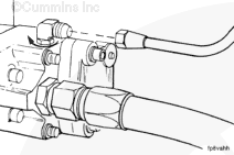
ActionMeasure the pressure. Measure the priming pump pressure at the quick connect fitting located on the top of the fuel pump. |
|
|
Does the pressure meet the 69 kPa [10 psi]? |
|
| YES | NO |
| No Repair |
Replace the priming pump.
NOTE: ISM engines are |
|
Repair complete
|
|
| Guided Step 3E – Check for coolant in the EGR transfer tube. | |
|---|---|
Conditions
ActionRemove the EGR transfer hose from the EGR cooler outlet. |
|
|
Is coolant present in the crossover tube? |
|
| YES | NO |
|
See the Coolant Loss – Internal symptom tree. |
No Repair |
|
Repair complete
|
Perform next troubleshooting procedure as outlined in Step 2
|
Guided Step 4 – Fuel system checks.
| Guided Step 4A – Check for air in the fuel. | ||
|---|---|---|
Conditions
ActionConnect the equipment to the fuel pump as shown. |
|
|
|
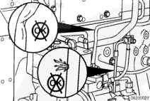
Air bubbles visible in the sight glass? |
||
| YES | NO | |
|
Locate and correct cause of air ingestion in OEM fuel supply system or damaged fuel filter sealing ring. Check the ECM cooling plate, associated plumbing, and o-ring seals for failures that can cause air ingestion. Repair or replace the malfunctioned component. Use the following procedure in the ISM, ISMe, and QSM11 Engines, Service Manual, Bulletin 3666322. |
No Repair | |
|
Repair complete
|
||
| Guided Step 4B – Check fuel inlet restriction. | ||
|---|---|---|
Conditions
ActionCheck the fuel inlet restriction. Use the following procedure in the ISM, ISMe, and QSM11 Engines, Service Manual, Bulletin 3666322. |
|
|
|
Is fuel inlet restriction less than the specifications listed below? Dirty – 254 mm-Hg [10 in-Hg]; |
||
| YES | NO | |
| No Repair |
Locate the cause of high fuel inlet restriction. Check the prefilter and fuel supply lines. |
|
|
Repair complete
|
||
| Guided Step 4C – Check drain line restriction. | ||
|---|---|---|
Conditions
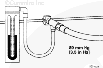
ActionObserve the reading on the pressure gauge. |
|
|
|
Is fuel drain line restriction less than 89 mm-Hg [3.5 in-Hg]? |
||
| YES | NO | |
| No Repair |
Locate cause of high fuel drain line restriction in OEM fuel return line. |
|
|
Repair complete
|
||
| Guided Step 4D – Check pump output pressure. | ||
|---|---|---|
Conditions
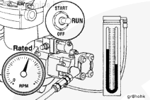
ActionObserve the reading on the pressure gauge. Read the fuel pressure while cranking if the engine will
|
|
|
|
Does the fuel pressure meet the specification? |
||
| YES | NO | |
| No Repair | No Repair | |
| Guided Step 4E – Check fuel gear pump check valve. | ||
|---|---|---|
Conditions
ActionInspect the fuel gear pump check valve for correct installation and operation. Use the following procedure in the ISM, ISMe, and QSM11 Engines, Service Manual, Bulletin 3666322. |
|
|
|
Is check valve installed and operating correctly? |
||
| YES | NO | |
|
Replace the fuel pump. Use the following procedure in the ISM, ISMe, and QSM11 Engines, Service Manual, Bulletin 3666322. |
Install the check valve correctly or replace the fuel gear pump check valve, if necessary. Use the following procedure in the ISM, ISMe, and QSM11 Engines, Service Manual, Bulletin 3666322. |
|
|
Repair complete
|
Repair complete
|
|
| Guided Step 4F – Check fuel supply line for restrictions. | ||
|---|---|---|
Conditions
ActionCheck the fuel line between the fuel pump and cylinder head for obstructions. Check the fuel line for sharp bends or kinks that could cause a restriction. |
|
|
|
Are fuel lines free from restrictions? |
||
| YES | NO | |
| No Repair |
Remove obstructions from fuel lines. Replace kinked or restricted lines as necessary. |
|
|
Repair complete
|
||
| Guided Step 4G – Check for plugged fuel drillings in the cylinder head. | ||
|---|---|---|
Conditions
ActionIf a ReCon® cylinder head was installed, check that the plastic insert has been removed from the fuel supply inlet passage in the cylinder head. |
|
|
|
Has plastic insert been removed from the fuel supply passage in the cylinder head? |
||
| YES | NO | |
| No Repair |
Remove the plastic insert from the fuel supply passage in the cylinder head. Use the following procedure in the ISM, ISMe, and QSM11 Engines, Service Manual, Bulletin 3666322. |
|
|
Perform the next troubleshooting procedure as outlined in Step 2
|
Repair complete
|
|
Guided Step 5 – Injector diagnostics.
| Guided Step 5A – Perform the INSITE™ electronic service tool cylinder cutout test. | |
|---|---|
Conditions
ActionPerform INSITE™ electronic service tool cylinder cutout test. |
|
|
Do all cylinders pass the cylinder cutout test? |
|
| YES | NO |
| No Repair |
Replace the injectors as needed. Use the following procedure in the ISM, ISMe, and QSM11 Engines, Service Manual, Bulletin 3666322. |
|
Perform next troubleshooting procedure as outlined in Step 2
|
Repair complete
|
Guided Step 6 – Air handling diagnostic checks.
| Guided Step 6A – Start engine and read fault codes. | |
|---|---|
Conditions
ActionCheck the fault codes with the engine running.
|
|
|
Active fault codes? |
|
| YES | NO |
| No Repair | No Repair |
|
Appropriate fault code troubleshooting tree
|
|
| Guided Step 6B – Inspect the turbocharger blades for damage. | |
|---|---|
Conditions
ActionInspect the compressor and turbine fins for damage or wear. |
|
|
Damage found on turbocharger fins? |
|
| YES | NO |
|
Replace the turbocharger. Use the following procedure in the ISM, ISMe, and QSM11 Engines, Service Manual, Bulletin 3666322. |
No Repair |
|
Repair complete
|
Perform the next troubleshooting procedure as outlined in Step 2.
|
Guided Step 7 – Check EGR system for proper operation.
| Guided Step 7A – Check for EGR related fault codes. | |
|---|---|
Conditions
ActionCheck for any EGR related fault codes. |
|
|
EGR related fault codes present? |
|
| YES | NO |
|
Troubleshoot electronic fault codes. |
No Repair |
|
Appropriate fault code troubleshooting trees
|
|
| Guided Step 7B – Check for inactive EGR Differential Pressure Sensor fault codes. | |
|---|---|
Conditions
ActionCheck for active fault codes.
|
|
|
Fault Code 1866, 2273, or 2274 active? |
|
| YES | NO |
| No Repair | No Repair |
|
Appropriate fault code troubleshooting tree.
|
|
| Guided Step 7C – Check the EGR differential pressure tubes for leaks. | |
|---|---|
Conditions
ActionCheck the lines for leaks.
|
|
|
Leaks detected at either the low or high EGR differential pressure tubes? |
|
| YES | NO |
|
Tighten the fittings, or replace the EGR differential pressure tube. Use the following procedure in the ISM, ISMe, and QSM11 Engines, Service Manual, Bulletin 3666322. |
No Repair |
|
Repair complete
|
|
| Guided Step 7D – Check the EGR differential pressure sensor adapter for leaks. | |
|---|---|
Conditions
ActionInspect the EGR differential pressure sensor adaptor for leaks.
|
|
|
Leaks detected at the EGR differential pressure sensor adapter? |
|
| YES | NO |
|
Replace the EGR differential pressure sensor adapter. Use the following procedure in the ISM, ISMe, and QSM11 Engines, Service Manual, Bulletin 3666322. |
No Repair |
|
Repair complete
|
|
| Guided Step 7E – Check the EGR differential pressure tubes for plugging. | |
|---|---|
Conditions
ActionInspect the EGR differential pressure tubes for restrictions, soot plugging and plugging.
|
|
|
Debris or soot found in either EGR differential pressure tube? |
|
| YES | NO |
|
Clear the debris or replace the EGR differential pressure tube. Use the following procedure in the ISM, ISMe, and QSM11 Engines, Service Manual, Bulletin 3666322. |
No Repair |
|
Repair complete
|
|
| Guided Step 7F – Check for air leaks in the EGR system. | |
|---|---|
ActionCheck for leaks in the EGR connection tubing and connections. Soot streaks are noticeable where leaks are present. |
|
|
Air leaks found in the EGR connection tubing? |
|
| YES | NO |
|
Repair any leaks in the EGR system. |
No Repair |
|
Repair complete
|
Perform next troubleshooting procedure as outlined in Step 2
|
Guided Step 8 – Verify electronic features are operating correctly.
| Guided Step 8A – Verify accelerator pedal travel. | |
|---|---|
Conditions
ActionUse INSITE™ electronic service tool to monitor Percent Accelerator while fully depressing and releasing the accelerator pedal. |
|
|
Does the Percent Accelerator read 0 when the accelerator is released and 100 percent when the accelerator is depressed? |
|
| YES | NO |
| No Repair |
Determine and correct cause of accelerator pedal restriction. |
|
Repair complete
|
|
| Guided Step 8B – Monitor vehicle speed. | |
|---|---|
Conditions
ActionUse INSITE™ electronic service tool to monitor Vehicle Speed while the vehicle is not moving. |
|
|
Does the vehicle speed read 0 when the vehicle is |
|
| YES | NO |
| No Repair |
Check the vehicle speed sensor and circuit or locate the cause of the vehicle speed interference. |
|
Repair complete
|
|
| Guided Step 8C – Verify electronic feature settings are correct. | |
|---|---|
Conditions
ActionUse INSITE™ electronic service tool to verify the following adjustable parameters are correctly set:
|
|
|
Are the electronic features set correctly? |
|
| YES | NO |
| No Repair |
Correct programmable features. |
|
Repair complete
|
|
| Guided Step 8D – Check ambient air pressure sensor accuracy | |
|---|---|
Conditions
ActionCheck for correct barometric pressure reading. Compare the barometric pressure sensor reading on INSITE™ electronic service tool data monitor/logger to the current local barometric pressure. |
|
|
Is the barometric pressure sensor reading in the INSITE™ electronic service tool within 5 percent of the present local barometric pressure reading? |
|
| YES | NO |
| No Repair |
Replace the ambient air pressure sensor. Use the following procedure in the ISX CM871 and ISM CM876 Electronic Control Systems, Troubleshooting and Repair Manual, Bulletin 4021560. |
|
Repair complete
|
|
| Guided Step 8E – Check the intake manifold pressure sensor accuracy. | |
|---|---|
Conditions
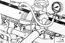
ActionConnect a mechanical intake manifold pressure gauge to the engine, as close to the intake manifold pressure sensor as possible.
|
|
|
INSITE™ electronic service tool reading within 17 kPa [2.5 psi] of mechanical gauge reading? |
|
| YES | NO |
| No Repair |
Remove and clean the intake manifold pressure sensor. Use the following procedure found in the ISX CM871 and ISM CM876 Electronic Control System, Bulletin 4021560. |
|
Perform the next troubleshooting procedure as outlined in Step 2
|
Repair complete
|
Guided Step 9 – Perform base engine mechanical checks.
| Guided Step 9A – Verify overhead adjustments are correct. | |
|---|---|
Conditions
ActionMeasure the overhead settings.
|
|
|
Are the overhead settings within the reset limits? |
|
| YES | NO |
| No Repair |
Adjust the overhead settings. Use the following procedure in the ISM, ISMe, and QSM11 Engines, Service Manual, Bulletin 3666322. |
|
Repair complete
|
|
| Guided Step 9B – Verify engine brake adjustment. | |
|---|---|
Conditions
ActionVerify the engine brakes are operating correctly.
|
|
|
Are the engine brake settings within the reset limits? |
|
| YES | NO |
| No Repair |
Adjust the engine brakes settings. Use the following procedure in the ISM, ISMe, and QSM11 Engines, Service Manual, Bulletin 3666322. |
|
Repair complete
|
|
| Guided Step 9C – Check air intake restriction. | |
|---|---|
Conditions
ActionCheck the intake system restriction by installintg a vacuum gauge or water manometer into the air intake system. Use the following procedure in the ISM, ISMe, and QSM11 Engines, Service Manual, Bulletin 3666322. |
|
|
Is air intake restriction greater than 635 mm-H |
|
| YES | NO |
|
Correct the cause of high intake air restriction. Check for plugged air filter or restricted air intake piping. |
No Repair |
|
Repair compete
|
|
| Guided Step 9D – Check exhaust restriction. | ||
|---|---|---|
Conditions
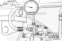
ActionCheck exhaust restriction by installing a pressure gauge into the exhaust system just past the turbocharger outlet. Use the following procedure in the ISM, ISMe, and QSM11 Engines, Service Manual, Bulletin 3666322. |
|
|
|
Is exhaust restriction greater than 304.8 mm-Hg [12.0 in-Hg]? |
||
| YES | NO | |
|
Remove the exhaust aftertreatment system from the vehicle and inspect for reuse. Use the following procedure in the ISM, ISMe, and QSM11 Engines, Service Manual, Bulletin 3666322. Inspect the aftertreatment system for a potential malfunction. |
No Repair | |
|
Repair complete
|
||
;)
;)
;)
;)
;)
;)
;)
;)
;)
;)
;)
;)
;)
;)
;)
;)
;)
;)
;)
;)
;)
;)
;)
;)
| Guided Step 9E – Inspect charge-air cooler | |
|---|---|
Conditions
ActionPressure test the charge-air cooler. Use the following procedure in the ISM, ISMe, and QSM11 Engines, Service Manual, Bulletin 3666322. |
|
|
Is the pressure drop 34 kPa [5 psi] or less in 15 seconds? |
|
| YES | NO |
| No Repair |
Repair or replace the charge air cooler assembly. |
|
Repair complete
|
|
| Guided Step 9F – Verify engine blowby is within specification. | |
|---|---|
Conditions
ActionLoad engine to rated rpm on a chassis dynamometer.
|
|
|
Are the engine blowby measurements within specification? |
|
| YES | NO |
| No Repair | No Repair |
|
Perform the next troubleshooting procedure as outlined in Step 2
|
|
| Guided Step 9F-1 – Verify turbocharger contribution to engine blowby. | |
|---|---|
Conditions
ActionLoad engine to rated rpm on a chassis dynamometer
|
|
|
Did the total engine blowby drop more than 30 percent? |
|
| YES | NO |
|
Replace the turbocharger assembly. Use the following procedure in the ISM, ISMe, and QSM11 Engines, Service Manual, Bulletin 3666322. |
Engine rebuild is possible. See the engine rebuild specifications. |
|
Repair complete
|
Repair complete
|
Guided Step 10 – Aftertreatment Checks
| Guided Step 10A – Check for aftertreatment related fault codes. | |
|---|---|
Conditions
ActionUse INSITE™ electronic service tool to read the fault codes. Check for any aftertreatment fault codes. Specifically fault codes related to high soot in the aftertreatment diesel particulate filter, face plugging of the aftertreatment diesel oxidation catalyst, and aftertreatment diesel oxidation catalyst efficiency. |
|
|
Fault codes related to the aftertreatment system are found to be active? |
|
| YES | NO |
| No Repair |
Correct the malfunction and verify complaint is no longer present after repair. |
|
Appropriate fault code troubleshooting tree
|
|
| Guided Step 10B – Perform basic aftertreatment troubleshooting checks | |
|---|---|
ConditionsNone ActionThe following items must be checked or verified before continuing:
|
|
|
All parts have been inspected, and appear to be functioning properly? |
|
| YES | NO |
| No Repair |
Correct the malfunction and verify complaint is no longer present after repair. |
|
Repair complete
|
|
| Guided Step 10C – Check for signs of internal damage to the aftertreatment system. | |
|---|---|
Conditions
ActionQuickly snap the throttle pedal accelerating the engine from low idle to high idle while checking for smoke at the exhaust outlet. Inspect the following during the snap throttle acceleration:
If the aftertreatment system is operating correctly, no visible smoke will be present during the snap throttle acceleration. Any visible smoke is an indication of a possible malfunction in the aftertreatment system. |
|
|
Any visible smoke (black or white) is present during the snap throttle acceleration? |
|
| YES | NO |
|
Any malfunction in the aftertreatment system: Remove the exhaust gas aftertreatment system form the vehicle and inspect for reuse. Use the following procedure in the ISM, ISMe, and QSM11 Engines, Service Manual, Bulletin 3666322. Inspect the aftertreatment system for a potential malfunction. |
No Repair |
|
Repair complete, troubleshoot the smoke complaint , use the proper TT tree steps
|
|
| Guided Step 10D – Check exhaust restriction. | ||
|---|---|---|
Conditions
ActionCheck exhaust restriction by installing a pressure gauge into the exhaust system just past the turbocharger outlet. If a port is not found in the exhaust system, remove the exhaust gas temperature 1 sensor and install the pressure gauge in the temperature sensor port. Use the following procedure in the ISM, ISMe, and QSM11 Engines, Service Manual, Bulletin 3666322. |
|
|
|
Is exhaust restriction greater than 304.8 mm-Hg [12.0 in-Hg]? |
||
| YES | NO | |
|
Remove the exhaust aftertreatment system from the vehicle and inspect for reuse. Use the following procedure in the ISM, ISMe, and QSM11 Engines, Service Manual, Bulletin 3666322. Inspect the aftertreatment system for a potential malfunction. |
No Repair | |
|
Repair complete
|
Perform the next troubleshooting procedure as outlined in Step 2.
|
|