ISM, ISMe, and QSM11 – 011-056   Exhaust System Diagnostics

View Related Topic


Table of Contents

General Information

General Information

TOC

The following procedure contains troubleshooting steps and information regarding the aftertreatment system.

 
SMALL | MEDIUM | LARGE


Leaks in the exhaust system can cause exhaust odor or white smoke.

Inspect the exhaust piping for leaks, cracks, and loose connections.
Refer to Procedure 010-024 (Air Leaks, Air Intake and Exhaust Systems) in Section 10.

Tighten the exhaust clamps, if necessary. Refer to the OEM specifications and the correct torque value.

It may be necessary to perform a stationary (parked) regeneration to locate exhaust leaks.
Refer to Procedure 014-013 (Aftertreatment Testing) in Section 14.

SMALL | MEDIUM | LARGE


The ambient temperature affects the length of time it will take to perform a stationary (parked) regeneration because the engine must work harder to increase the exhaust temperatures to the appropriate levels in cold ambient temperatures.

In cold ambient temperatures (approximately -18°C [0°F] or colder), stationary (parked) regeneration may take longer to complete. In extremely cold ambient temperatures, stationary (parked) regeneration may
not complete.

In these cases, it may be necessary to warm the engine to operating temperature before starting the stationary (parked) regeneration, or to move the vehicle to a location with higher ambient temperatures.

 
SMALL | MEDIUM | LARGE


The vehicle manufacturer has the option of installing two switches that control aftertreatment function: the start switch and the permit switch.

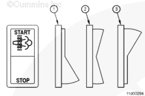
The start switch (called the Diesel Particulate Filter Regeneration Start Switch in INSITE™ electronic service tool) is used to start a stationary (parked) regeneration. The vehicle manufacturer may also reference this switch as a “stationary regeneration switch,” “start switch,” or “parked regeneration switch”.

The permit switch (called the Diesel Particulate Filter Permit Switch in INSITE™ electronic service tool) is used to allow the operator to disable active regeneration, if necessary. The vehicle manufacturer may also reference this switch as an “inhibit switch,” “stop switch,” or “disable switch”.

The start switch can be hardwired to the ECM, or it can be multiplexed over J1939 multiplexing.

If the start switch is hardwired, it shares an ECM pin with the diagnostic switch. When the switch is turned ON and the engine is OFF, the ECM interprets this signal as the diagnostic switch. When the switch is turned ON and the engine is running, the ECM interprets this signal as the start switch.

If the start switch is J1939-multiplexed, the signal for this switch is broadcast over the J1939 data link.

A J1939-multiplexed start switch signal has priority over a hardwired start switch signal, therefore if the start switch is enabled over J1939, the hardwired signal is ignored by the engine ECM.

The default setting for the start switch is OFF. If the start switch is enabled to INSITE™ electronic service tool, but no switch is installed (either hardwired of J1939-multiplexed), the switch status will remain OFF.

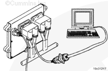
The position of the start switch can be monitored with INSITE™ electronic service tool in the data monitor/logger screen.

The default setting for the permit switch is ENABLED.

If the permit switch is enabled with INSITE™ electronic service tool, but no switch is installed (either hardwired or J1939 multiplexed), the switch status will remain OFF.

If the vehicle is operated for an extended period of time with the permit switch OFF, fault codes for the above normal levels of aftertreatment diesel particulate filter soot load may result (Fault Codes 1921, 1922, and 2639).

If the aftertreatment diesel particulate filter soot load reaches the moderately severe level (Fault Code 2639), and the permit switch is OFF, the ECM will also log a Fault Code 2777.

If the permit switch is multiplexed, and therefore ENABLED, in the J1939 section of Features and Parameters in INSITE™ electronic service tool, it
must also be enabled in the aftertreatment section of Features and Parameters in INSITE™ electronic service tool. If is is
not, regeneration will be inhibited.

The permit switch can be hardwired to the ECM
only in emergency vehicle calibrations. For all other non-emergency calibrations, the permit switch can
only be J1939-multiplexed over the J1939 data link.

In emergency vehicle calibrations where the permit switch is hardwired, the permit switch replaces the governor type switch.

A J1939-multiplexed permit switch signal has priority over a hardwired start switch signal, so if the permit switch is enabled over J1939, the hardwired signal is ignored by the engine ECM.

The position of the permit switch can be monitored with INSITE™ electronic service tool in the data monitor/logger screen:

  • When the permit switch is ON, active regeneration is allowed.
  • When the permit switch is OFF, active regeneration is
    not allowed.
 
SMALL | MEDIUM | LARGE


If the aftertreatment exhaust gas temperature sensors are
not connected properly, or if the wiring in the harness between the engine and aftertreatment is
not correct, the engine may experience frequent DPF lamp illuminations, or stationary (parked) regenerations that do
not complete.

Inspect the exhaust aftertreatment temperature sensor connectors to verify they are connected to the correct connector on the aftertreatment system wiring harness. Two of the temperature sensors have identical wiring harness connectors. Because the sensors are the same part number, it is possible to install the wiring harness connectors to the wrong sensor.

To verify the correct sensor locations, use INSITE™ electronic service tool to monitor the following parameters with the ignition key ON, but with the engine
not running.

  • Aftertreatment Diesel Oxidation Catalyst Inlet Temperature Sensor Signal Voltage (V)
  • Aftertreatment Diesel particulate Filter Inlet Temperature Sensor Signal Voltage (V)
  • Aftertreatment Diesel Particulate Filter Outlet Temperature Sensor Signal Voltage (V).

Unplug each of the aftertreatment exhaust gas temperature sensors, one at a time.

If the voltage changes when the sensor is unplugged, the wiring harness connector is connected to the correct sensor.

If the voltage does
not change when the sensor is unplugged, switch the connector location to the other temperature sensor, unplug it, and check for a voltage change.

An incorrectly assembled aftertreatment wiring harness can
not be checked by unplugging each of the aftertreatment exhaust gas temperature sensors.

The
only method to check for a misassembled aftertreatment wiring harness is to check the wiring harness connectors for correct pin installation. Refer to the engine wiring diagram for connector pin identification and location.

SMALL | MEDIUM | LARGE


When performing a stationary (parked) regeneration, monitor the exhaust temperatures in the aftertreatment to determine why a stationary (parked) regeneration will
not complete.

Possible causes for stationary (parked) regenerations that will
not complete include:

  • Misassembled aftertreatment wiring harness
  • Aftertreatment exhaust gas temperature sensors installed in the wrong location
  • A plugged aftertreatment diesel oxidation catalyst
  • A malfunctioning turbocharger.

A normal stationary (parked) regeneration will follow the pattern shown.

  • The dashed line is for the aftertreatment diesel oxidation catalyst inlet temperature sensor.
  • The dotted line is for the aftertreatment diesel particulate filter inlet temperature sensor.
  • The solid line is for the aftertreatment diesel particulate filter outlet temperature sensor.

When the stationary (parked) regeneration begins (1), all three temperatures should be approximately the same, and should increase at the same rate.

The wiring to the aftertreatment temperature sensors appears to be correct in this example because they all read approximately the same temperature at the beginning of the stationary (parked) regeneration and increase at the same rate.

Aftertreatment injection begins when all three temperatures reach approximately 288°C [550°F] (2).

Once aftertreatment injection begins, the aftertreatment diesel oxidation catalyst inlet temperature may vary slightly, but will typically remain between 260 and 399°C [500 and 750°F].

The aftertreatment diesel particulate filter inlet and outlet temperatures will increase to approximately 482 to 649°C [900 to 1200°F]. The temperatures may vary during the stationary (parked) regeneration as the amount of fuel injected during aftertreatment injection is changed to maintain a constant temperature.

The aftertreatment diesel particulate filter inlet and outlet temperatures will remain at this temperature for the duration of the stationary (parked) regeneration.

 
SMALL | MEDIUM | LARGE


This graph illustrates a stationary (parked) regeneration where the inlet of the aftertreatment diesel oxidation catalyst is blocked.

  • The dashed line is for the aftertreatment diesel oxidation catalyst inlet temperature sensor.
  • The dotted line is for the aftertreatment diesel particulate filter inlet temperature sensor.
  • The solid line is for the aftertreatment diesel particulate filter outlet temperature sensor.

In this condition, the engine speed will increase to the stationary (parked) regeneration speed of 1000 to 1400 rpm.

Raising the aftertreatment temperature to the aftertreatment injection temperature may take longer to complete than normal if the inlet to the aftertreatment diesel oxidation catalyst is plugged, restricting some of the exhaust flow.

Once aftertreatment injection begins (2), the aftertreatment diesel particulate filter inlet and outlet temperatures will differ greatly due to the plugged aftertreatment diesel oxidation catalyst being unable to oxidize the injected fuel. The aftertreatment diesel particulate filter has some capability to oxidize the injected fuel, but can
not maintain this condition without damaging the filter material over time. It is possible that white smoke would be present from the vehicle tailpipe during this condition.

The wiring to the aftertreatment temperature sensors appears to be correct in this example because they all read approximately the same temperature at the beginning of the stationary (parked) regeneration and they increase at the same rate.

The possible cause of this condition is a plugged aftertreatment diesel oxidation catalyst.
Refer to Procedure 011-049 (Aftertreatment Diesel Oxidation Catalyst) in Section 11 to inspect the aftertreatment diesel oxidation catalyst.

 
SMALL | MEDIUM | LARGE


This graph illustrates a stationary (parked) regeneration where the engine can
not build enough heat to start aftertreatment injection.

  • The dashed line is for the aftertreatment diesel oxidation catalyst inlet temperature sensor.
  • The dotted line is for the aftertreatment diesel particulate filter inlet temperature sensor.
  • The solid line is for the aftertreatment diesel particulate filter outlet temperature sensor.

The engine speed will likely increase to the stationary (parked) regeneration speed of 1000 to 1400 rpm, but because the aftertreatment temperatures do
not increase enough to start aftertreatment injection, the stationary (parked) regeneration will
not complete.

The wiring to the aftertreatment temperature sensor appears to be correct in this example because they all read approximately the same temperature for the same conditions.

Possible causes of this issue include:

 
SMALL | MEDIUM | LARGE


This graph illustrates a stationary (parked) regeneration where the wiring to the aftertreatment temperature sensors is incorrect.

  • The dashed line is for the aftertreatment diesel oxidation catalyst inlet temperature sensor.
  • The dotted line is for the aftertreatment diesel particulate filter inlet temperature sensor.
  • The solid line is for the aftertreatment diesel particulate filter outlet temperature sensor.

In this condition, the engine speed will increase to the stationary (parked) regeneration speed of 1000 to 1400 rpm.

Aftertreatment injection will
not occur in this condition because the aftertreatment diesel oxidation catalyst inlet temperature does
not reach the required temperature. Because aftertreatment injection is
not occurring, the aftertreatment temperatures should
not read differently.

The possible cause of this condition is an incorrectly assembled aftertreatment wiring harness. See the aftertreatment exhaust gas temperature sensor wiring section of this procedure.

 
SMALL | MEDIUM | LARGE


This graph illustrates a stationary (parked) regeneration where the connectors to the aftertreatment diesel oxidation catalyst inlet temperature sensor and the aftertreatment diesel particulate filter outlet temperature sensor are reversed.

  • The dashed line is for the aftertreatment diesel oxidation catalyst inlet temperature sensor.
  • The dotted line is for the aftertreatment diesel particulate filter inlet temperature sensor.
  • The solid line is for the aftertreatment diesel particulate filter outlet temperature sensor.

In this condition, the engine speed will increase to the stationary regeneration speed of 1000 to 1400 rpm.

Aftertreatment injection may occur in this condition (2). However, the aftertreatment diesel oxidation catalyst inlet temperature increases after aftertreatment injection begins, while the aftertreatment diesel particulate filter outlet temperature remains constant.

The possible cause of this condition is that the connectors to the aftertreatment diesel oxidation catalyst inlet temperature sensor and the aftertreatment diesel particulate filter outlet temperature sensor are reversed. See the aftertreatment exhaust gas temperature sensor wiring section of this procedure.

 
SMALL | MEDIUM | LARGE
Last Modified:  28-May-2008