Batteries can emit explosive gases. To reduce the possibility of personal injury, always ventilate the compartment before servicing the batteries. To reduce the possibility of arcing, remove the negative (-) battery cable first and attach the negative (-) battery cable last.
Batteries can emit explosive gases. To reduce the possibility of personal injury, always ventilate the compartment before servicing the batteries. To reduce the possibility of arcing, remove the negative (-) battery cable first and attach the negative (-) battery cable last.
NOTE: Prior to starting this procedure, make sure that there is adequate clearance in front of the engine. Make sure there is plenty of clearance from the front gear housing face to any obstruction in the camshaft area to remove the camshaft. If not, the engine must be removed from the vessel.
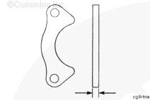
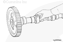
NOTE: Because the thrust plate extends more than 180 degrees around the camshaft, the thrust plate can only be removed from the camshaft after removing the cam gear from the camshaft.
Refer to Camshaft Reuse Guidelines for Cummins® Engines with Roller Followers or Roller Tappets, Bulletin3666052 for reuse guidelines for roller tappet and steel camshafts.
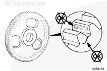
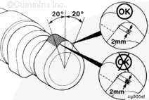
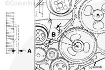
The area of edge deterioration must not be greater than the equivalent area of a 2 mm [0.079 in] circle within ± 20 degrees of the nose of the cam lobe.
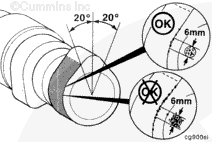
Outside of the ± 20 degrees of the nose of the cam lobe, the areas of edge deterioration must not be greater than the equivalent area of a 6 mm [0.236 in] circle.
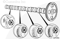
NOTE: If the camshaft shows any pitting or wear, remove and inspect the tappets before installing the camshaft. Refer to Procedure 004-015 in Section 4. If a new camshaft is installed on an engine that uses slider tappets, new tappets and push tubes also must be installed. If a new camshaft is installed on an engine that uses roller tappets, only the damaged roller tappets must be replaced.
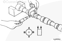
Do not try to force the camshaft into the camshaft bore as damage to the camshaft bushing can result.
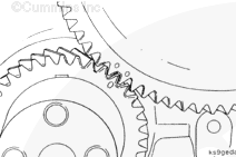
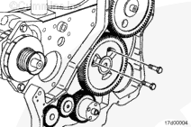
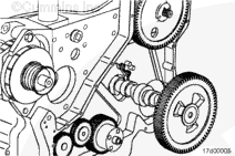
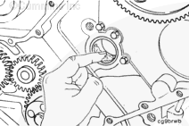
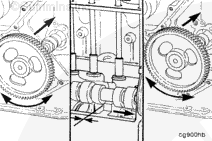
Install the camshaft. While pushing in slightly, rotate the camshaft and carefully work the camshaft through the camshaft bushings. As each camshaft journal passes through a bushing, the camshaft will drop slightly and the camshaft lobes will catch on the bushings. Rotating the camshaft will free
the lobe from the bushing and allow the camshaft to be installed.
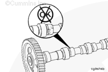
Before the camshaft gear engages the crankshaft gear, check the camshaft for ease of rotation. When installed properly, the camshaft must
rotate freely.
Batteries can emit explosive gases. To reduce the possibility of personal injury, always ventilate the compartment before servicing the batteries. To reduce the possibility of arcing, remove the negative (-) battery cable first and attach the negative (-) battery cable last.
Batteries can emit explosive gases. To reduce the possibility of personal injury, always ventilate the compartment before servicing the batteries. To reduce the possibility of arcing, remove the negative (-) battery cable first and attach the negative (-) battery cable last.
Hello, I'm Jack, a diesel engine fan and a blogger. I write about how to fix and improve diesel engines, from cars to trucks to generators. I also review the newest models and innovations in the diesel market. If you are interested in learning more about diesel engines, check out my blog and leave your feedback.
View all posts by Jack
 WARNING


 CAUTION


;)
;)
;)
;)
;)
;)
;)
;)
;)
;)
;)
;)
;)
;)
;)
;)
;)
;)
;)
;)
;)
;)
;)
;)
;)
;)
;)
;)
;)
;)
;)
;)