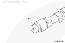
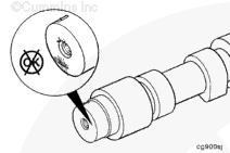
NOTE: Because the thrust plate extends more than 180 degrees around the camshaft, the thrust plate must be installed before installing the cam gear on the camshaft.
Wear protective gloves to reduce the possibility of personal injury when handling parts that have been heated.
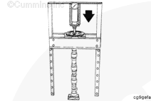
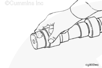
NOTE: When clamping the camshaft to install the gear, do not place clamps directly on the camshaft lobes or journals, which could damage the surfaces. Clamp only the cast surfaces between the lobes, or place padding between the clamps and the camshaft surfaces.
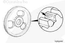
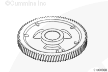
Install the camshaft gear with the timing marks away from the camshaft.
NOTE: Be sure the gear is seated against camshaft shoulder.
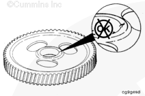
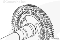
Use a 0.02 mm [0.001 in] feeler gauge, to see if the feeler gauge can be inserted between the camshaft gear and the shoulder on the camshaft. If the feeler gauge can be inserted, the camshaft gear is not properly seated.
Hello, I'm Jack, a diesel engine fan and a blogger. I write about how to fix and improve diesel engines, from cars to trucks to generators. I also review the newest models and innovations in the diesel market. If you are interested in learning more about diesel engines, check out my blog and leave your feedback.
View all posts by Jack


 CAUTION
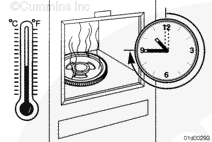
 WARNING
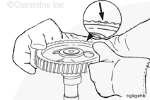


;)
;)
;)
;)
;)
;)
;)
;)
;)
;)
;)
;)
;)
;)
;)
;)
;)
;)
;)
;)
;)
;)
;)
;)