Be sure to tie the exhaust piping up above the water line to prevent water from feeding back into the vessel while the exhaust piping is removed. Failure to do so can result in the vessel sinking.
Remove the exhaust pipe from the turbocharger. See the Remove section in this procedure.
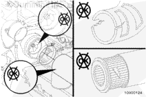
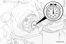
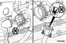
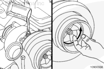
With the feeler gauge in the same location, gently push the turbocharger compressor wheel away from the turbocharger compressor housing and measure the clearance between the compressor wheel and housing.
Subtract the smaller clearance from the larger clearance. This is the radial bearing clearance.
Radial Bearing Clearance (HX55 – Wastegate, Water Cooled)
mm
in
0.044
MIN
0.0172
0.608
MAX
0.0239
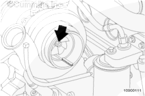
For variable geometry turbochargers, check the radial movement of the rotor system by pushing the turbocharger compressor wheel toward the wall of the compressor cover with light finger pressure. The turbocharger passes inspection if the wheel does not contact the compressor cover wall.
Repeat the procedure on the turbocharger turbine wheel.
Replace the turbocharger if the radial bearing clearance does not meet specifications. See the Remove and Install sections in this procedure.
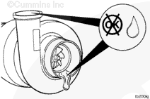
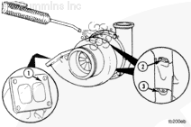
Inspect the turbocharger compressor intake and discharge for oil.
If oil is present in the compressor intake, as well as in the discharge, check upstream in the turbocharger for the source of the oil.
NOTE: Some marine engines have a closed crankcase breather system which is connected to the engine mounted air cleaner assembly. Check the closed crankcase breather system. Refer to Procedure 010-013 in Section 10.
If oil is present only in the discharge side, install the air intake and charge-air cooler piping, or the aftercooler piping. Refer to the OEM service manual. If equipped with an aftercooler, Refer to Procedure 010-005 in Section 10.
If oil is present only in the discharge side, install the air intake and charge-air cooler piping. Refer to OEM service manual.
NOTE: If the engine experiences a turbocharger failure that resulted in coolant, or oil entering the intake, the charge-air cooler system as well as the EGR differential pressure cross drillings should be inspected and cleaned. Use the following procedure for the charge-air cooler. Refer to Procedure 010-027 in Section 10. Use the following procedure for differential pressure cross drillings. Refer to Procedure 010-080 in Section 10.
If the crankcase pressure is within specifications, replace the turbocharger. See the Remove and Install sections in this procedure.
NOTE: If the engine experiences a turbocharger malfunction that results in coolant or oil entering the intake, the charge-air cooler system, as well as the EGR differential pressure cross drillings, are to be inspected and cleaned. Clean and inspect the charge-air cooler system. Refer to Procedure 010-027 in Section 10. Clean and inspect the EGR differential pressure cross drillings. Refer to Procedure 010-080 in Section 10.
NOTE: If the engine experiences a turbocharger malfunction or any other occasion where oil is put into the exhaust, the aftertreatment components must be inspected. Inspect the aftertreatment diesel oxidation catalyst. Refer to Procedure 011-049 in Section 11. Inspect the aftertreatment diesel particulate filter. Refer to Procedure 011-041 in Section 11.
Add 1 unit of fluorescent tracer, Part Number 3376891, to each 38 liters [10 gal] of engine lubricating oil.
Install the exhaust pipe to the turbocharger turbine outlet and tighten the clamp. See the Install section in this procedure, if the exhaust outlet is sea water cooled.
Install the intake pipe to the turbocharger compressor inlet and tighten the clamp. See the Install section in this procedure, if equipped with an engine mounted air cleaner.
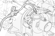
Locally manufacture a turbocharger coolant leak test kit to connect to the coolant inlet and outlet.
An air pressure regulator is required to control shop air pressure during the test.
A M14x1.5 male plug is required to block the water outlet.
A hose with an appropriate fitting to connect to the air pressure regulator and a 13/16”-16 female flat face o-ring fitting is required to connect to the water inlet.
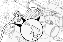
If the pressure decrease is more than 34 kPa [5 psi] in 1 minute, use a spray bottle of soapy water to wet all hose connections. Bubbles will appear if the connections are leaking.
If the pressure decreases and the hose connections are not leaking, replace the turbocharger.
Do not remove the pressure cap from a hot engine. Wait until the coolant temperature is below 50°C [120°F] before removing the pressure cap. Heated coolant spray or steam can cause personal injury.
WARNING
Coolant is toxic. Keep away from children and pets. If not reused, dispose of in accordance with local environmental regulations.
CAUTION
Use caution when draining oil or replacing filters that oil is not spilled or drained into the bilge area. The oil and oil filters must be discarded in accordance with local environmental regulations.
CAUTION
Use caution when draining coolant that coolant is not spilled or drained into the bilge area. Do not pump the coolant overboard. If the coolant is not reused, it must be discarded in accordance with local environmental regulations.
CAUTION
Be sure to tie the exhaust piping up above the water line to prevent water from feeding back into the vessel while the exhaust piping is removed. Failure to do so can result in the vessel sinking.
Shut off the sea water supply valve(s). Refer to the OEM service manual.
This component or assembly weights greater than 25kg [50 lb]. To prevent serious personal injury, be sure to have assistance or use appropriate lifting equipment to lift the component or assembly.
CAUTION
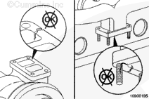
The gasket water ports are larger on the top and bottom passages. The gasket is also marked “Turbocharger” on the side facing the turbocharger. The gasket must be installed with the port size matching the ports of the exhaust manifold and turbocharger, and with the “Turbocharger” marking facing the turbocharger to prevent damage to the turbocharger from overheating.
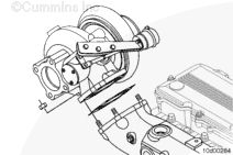
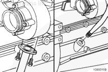
Remove the turbocharger mounting nuts and turbocharger.
When using solvents, acids, or alkaline materials for cleaning, follow the manufacturer’s recommendations for use. Wear goggles and protective clothing to reduce the possibility of personal injury.
WARNING
When using a steam cleaner, wear safety glasses or a face shield, as well as protective clothing. Hot steam can cause serious personal injury.
WARNING
Wear appropriate eye and face protection when using compressed air. Flying debris and dirt can cause personal injury.
Remove all carbon deposits and gasket material from surfaces.
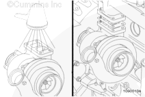
Use solvent or steam to clean the exterior of the turbocharger.
If cracks that go all the way through the outer walls are found, the turbocharger must be replaced.
NOTE: A charge air cooler failure can cause progressive damage to the turbine housing. If the turbine housing is damaged, check the charge air cooler. Refer to Procedure 010-027 in Section 10.
This component weighs 23 kg [50 lb] or more. To reduce the possibility of personal injury, use a hoist or get assistance to lift this component.
CAUTION
The gasket water ports are larger on the top and bottom passages. The gasket is also marked “Turbocharger” on the side facing the turbocharger. The gasket must be installed with the port size matching the port size of the exhaust manifold and turbocharger, and with the “Turbocharger” marking facing the turbocharger to prevent damage to the turbocharger from overheating.
Apply a film of high-temperature anti-seize compound to the turbocharger mounting studs.
Use a new gasket and install the turbocharger.
Install and tighten the four mounting nuts.
NOTE: The torque values given have been established using anti-seize compound as a lubricant.
Lubricate the bearings by pouring 59 to 89 ml [2 to 3 oz] of clean 15W40 engine oil into the turbocharger oil supply line fitting. Rotate the turbine wheel to allow oil to enter the bearing housing.
Hello, I'm Jack, a diesel engine fan and a blogger. I write about how to fix and improve diesel engines, from cars to trucks to generators. I also review the newest models and innovations in the diesel market. If you are interested in learning more about diesel engines, check out my blog and leave your feedback.
View all posts by Jack
 CAUTION


 WARNING


;)
;)
;)
;)
;)
;)
;)
;)
;)
;)
;)
;)
;)
;)
;)
;)
;)
;)
;)
;)
;)
;)
;)
;)
;)
;)
;)
;)
;)
;)
;)
;)
;)
;)
;)
;)
;)
;)
;)
;)
;)
;)
;)
;)
;)
;)
;)
;)
;)
;)
;)
;)
;)
;)