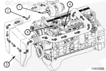
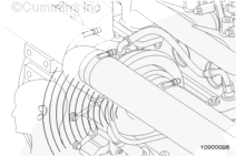
The combustion air system on the engine consists of an air cleaner, intake air piping, turbocharger, charge air piping, charge air cooler (CAC), and intake air heater.
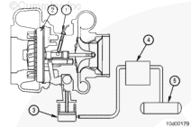
Air is drawn through the air cleaner and into the compressor side of the turbocharger (1). It is then forced through the CAC piping (2), to the CAC (3), the intake air heater (if applicable), and into the intake manifold (4). From the intake manifold, air is forced into the cylinders (5) and used for combustion.
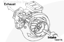
The turbocharger uses exhaust gas energy to turn the turbine wheel. The turbine wheel drives the compressor impeller that provides pressurized air to the engine for combustion. The additional air provided by the turbocharger allows more fuel to be injected to increase the power output from the engine.
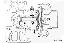
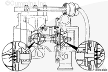
The turbine, compressor wheels, and shaft are supported by two rotating bearings in the bearing housing. Passages in the bearing housing direct filtered, pressurized engine oil to the shaft bearings and thrust bearings. The oil is used to lubricate and cool the rotating components. Oil then drains from the bearing housing to the engine sump, through the oil drain line.
An adequate supply of good, filtered oil is very important to the life of the turbocharger. Make sure a high-quality oil is used and that the oil and the oil filter are changed according to maintenance recommendations.
Wastegated turbochargers are used to optimize performance. The wastegated design allows maximum boost to be developed quickly, while making sure that the turbocharger does not overspeed at higher engine rpm.
Wastegate operation is controlled by an actuator that senses compressor pressure and balances it against a preset spring load. The wastegate valve is located in the turbine inlet passage. When open, it diverts a portion of the exhaust gas away from the turbine wheel, thereby controlling the shaft speed and boost.
Variable geometry turbochargers are used to improve engine performance by building boost more quickly during acceleration or transient conditions. A variable geometry turbocharger does not use a wastegate actuator. A pneumatic or electric actuator is used to vary the turbine exit area. By closing the variable geometry nozzle (reducing the turbine exit area), turbocharger speeds are increased and boost pressure increases more rapidly. By opening the variable geometry nozzle (increasing the turbine exit area), turbocharger speeds are lower and less boost pressure is produced.
Failure of the internal components of a malfunctioning turbocharger can reduce its effectiveness and also cause excessive smoke and low power. A bearing failure can produce friction that will slow the speed of the rotor assembly. Failed bearings can also allow the blades of the rotor assembly to rub the housings, thus reducing the rotor assembly speed.
A malfunctioning turbocharger wastegate , variable geometry turbocharger actuator, variable geometry turbocharger actuator controller, or miscalibration of the turbocharger wastegate can result in excessively high or low boost pressures. Low boost pressures can cause excessive smoke and low power. High boost pressures can cause major engine damage.
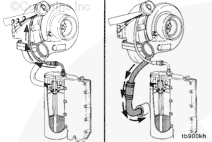
Engine lubricating oil is used to lubricate the bearings and provide some cooling for the turbocharger. The lubricating oil supplied to the turbocharger through the supply line is at engine operating pressure. A return line connected to the bottom of the turbocharger routes the lubricating oil back to the engine lubricating oil pan.
Seal rings are used on each end of the rotor assembly. The primary function of the seals is to prevent exhaust gases and compressed air from entering the turbocharger housing. Lubricating oil leakage from the seals is rare, but it can occur.
Excessive crankcase pressure can prevent oil from draining to the oil pan. This can load the bearing housing and cause lubricating oil to leak past the compressor seals and into the engine.
A restricted or damaged lubricating oil return line will cause the turbocharger housing to be pressurized, causing lubricating oil to migrate past the seals.
Additionally, high intake or exhaust restrictions can cause a vacuum between the compressor and the turbocharger housing, resulting in oil leaking past the seals.
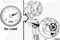
It is normal for the turbocharger to emit a whining sound that varies in intensity depending on engine speed and load. The sound is caused by the very high rotational speed of the rotor assembly and the method used to balance the rotor assembly during manufacturing. Consequently, the sound will be louder at full speed.
If possible, operate the engine at full speed to verify the noise level.
Variable geometry turbochargers can also emit a snorting or chuffing sound when the turbocharger operates under certain conditions. An example of this is when the turbocharger is at high speed and the throttle is rapidly closed. These sounds are normal and do not cause damage to or decrease the life of the turbocharger.
Leaks in the air system intake and/or exhaust components can produce excessive engine noise. Leak noise is typically a high pitched whine or sucking sound.
Automotive engines use a chassis-mounted charge air cooler (CAC) to improve engine performance and reduce emissions. This system also uses large-diameter piping to transfer the air from the engine turbocharger to the CAC, then returns the air from the CAC to the engine intake manifold.
The long-term integrity of the charge air cooling system is the responsibility of the vehicle and component manufacturers.
All ISL with CM850 engines utilize a variable geometry turbocharger to improve engine performance by building boost more quickly during acceleration or transient conditions. A pneumatic actuator is used to vary the turbine exit area allowing various boost levels based on performance needs. By closing the variable geometry nozzle (reducing turbine exit area), turbocharger speeds are increased and boost pressure increases more rapidly. By opening the variable geometry nozzle (increasing the turbine exit area), turbocharger speeds are lower and less boost pressure is produced.
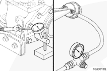
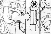
The variable geometry turbocharger functions as a standard turbocharger with the addition of the following:
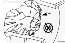
A speed sensor (1) in the bearing housing to monitor turbocharger operation
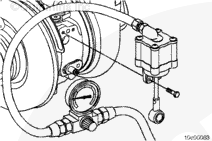
The sliding nozzle (2) is activated by a pneumatic actuator attached to the vehicle (brake) air supply system
The pneumatic actuator (3) operated by an air control valve (4) and receives air from the supply tank (5)
When the variable geometry turbocharger mechanism opens, a noise can be heard as the air is released from the actuator (3) through the control valve (4)
Water-cooled bearing housing in addition to oil lubrication.
It is normal for the turbocharger to emit a whining sound that varies in intensity depending on engine speed and load. The sound is caused by the very high rotational speed of the rotor assembly and the method used to balance the rotor assembly during manufacturing. Consequently, the sound will be louder at full speed. Also, the pneumatic actuator can emit a slight air leak at key-on position.
The variable geometry turbocharger control valve modulates air pressure to the variable geometry actuator. The electronic control module (ECM) sends a pulse width modulated signal to the turbocharger control valve to control the variable geometry turbocharger. As the signal increases, more air pressure is applied to the variable geometry actuator. Conversely, when the signal decreases, less air pressure is applied to the variable geometry actuator. The turbocharger control valve has both low and high voltage fault codes.
All ISC, QSC8.3, and QSL9 with CM850 engines utilize a Holset® wastegated turbocharger. The wastegate is pneumatically controlled by intake manifold pressure and factory calibrated. The wastegates are not adjustable in the field.
Hello, I'm Jack, a diesel engine fan and a blogger. I write about how to fix and improve diesel engines, from cars to trucks to generators. I also review the newest models and innovations in the diesel market. If you are interested in learning more about diesel engines, check out my blog and leave your feedback.
View all posts by Jack


;)
;)
;)
;)
;)
;)
;)
;)
;)
;)
;)
;)
;)
;)
;)
;)
;)
;)
;)
;)
;)
;)
;)
;)
;)
;)
;)
;)
;)
;)