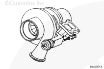
The wastegated turbocharger is a Holset® Model HX40. It is comprised of a turbocharger, wastegate actuator, and wastegate valve in the turbine housing. A wastegated turbocharger provides improved response at low engine speeds without sacrificing turbocharger durability at high speeds. This is accomplished by allowing the exhaust gases to bypass the turbine wheel during certain modes of engine operation. During low rpm operation, the turbocharger operates as a closed-system turbocharger where the energy of the gas is transferred to the compressor wheel and used to compress intake air. During high rpm operation however, the turbocharger becomes an open-system turbocharger and allows exhaust gas to bypass the turbine. Since the exhaust gas is gated around the turbine wheel, less energy is absorbed through the turbine and transferred to the compressor, reducing the intake manifold pressures and turbine speeds.
The wastegate actuator is mounted on the turbocharger and consists of a pressure canister, diaphragm, and rod. As the pressure changes in the canister, as dictated by the wastegate controller, the actuator rod adjusts the wastegate valve accordingly.
The wastegate valve is mounted inside the turbocharger in the turbine housing. As the valve opens, exhaust gas is allowed to bypass the turbine wheel, lowering turbine speed to adjust the intake manifold pressure.
Some engines are equipped with a diesel oxidation catalyst to reduce exhaust emissions.
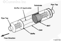
Typically, the diesel oxidation catalyst is contained within the muffler assembly and consists of a ceramic substrate that is treated with a chemical coating to oxidize particles of unburned fuel and oil.
The ceramic substrate is held in place in the muffler by a mat, which is a high temperature pad that surrounds the ceramic substrate within the metal muffler housing.
Some transit bus engines are equipped with an exhaust gas filter system, which is used to reduce the amount of particulate matter emitted from the exhaust.
The exhaust gas filter system consists of several components:
Exhaust catalyst
Exhaust gas temperature sensor
Exhaust gas pressure sensor
Exhaust gas treatment monitor unit and the exhaust gas treatment monitor unit harness
Exhaust gas treatment fault code and maintenance lamps.
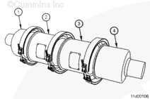
The exhaust catalyst is a modular assembly consisting of an inlet section (1), a catalyst section (2), an exhaust gas filter section (3), and an outlet section (4). All the sections are joined together with gaskets and v-band clamps.
The exhaust gas filter section captures the particulate matter in the exhaust, and then uses the heat generated by the reaction of the unburned fuel and oil particles in the catalyst section to oxidize the particulate matter.
The exhaust gas filter requires periodic maintenance to remove the ash that accumulates when the particulate matter oxidizes.
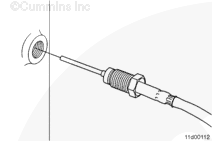
The exhaust gas temperature sensor is typically mounted in the inlet of the exhaust catalyst, however, it can be placed in the vehicle exhaust piping between the turbocharger and the exhaust catalyst inlet.
The exhaust gas temperature sensor monitors the temperature of the exhaust gas entering the exhaust catalyst.
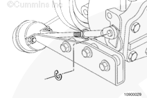
The exhaust gas pressure sensor is typically mounted to the vehicle near the exhaust catalyst and is connected to the inlet of the exhaust catalyst by a length of stainless steel flex tubing.
The exhaust gas pressure sensor monitors the exhaust restriction.
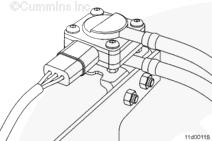
The exhaust gas treatment monitor unit and wiring harness are typically installed in the engine compartment of the vehicle.
The exhaust gas treatment monitor unit (1) monitors the exhaust restriction and exhaust temperature and provides the vehicle operator with feedback via the exhaust gas treatment fault code and maintenance lamps.
The exhaust gas treatment monitor unit harness (2) connects the exhaust gas treatment monitor unit to the exhaust gas temperature sensor, the exhaust gas pressure sensor, and the exhaust gas treatment fault code and maintenance lamps.
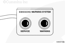
The exhaust gas treatment fault code and maintenance lamps are typically located on the vehicle dashboard within sight of the vehicle operator.
The exhaust gas treatment fault code and maintenance lamps alert the operator to electrical faults within the exhaust gas filter system. The lamps can also alert the operator to either excessive exhaust gas temperature or excessive exhaust restriction.
Both lamps will flash twice upon engine startup to signify that the exhaust gas filter system is operating properly.
The WARNING lamp is red and indicates the need to stop the engine as soon as it can be done safely. The engine must remain shutdown until the exhaust gas filter system can be repaired.
The SERVICE lamp is yellow. When it illuminates, the exhaust gas filter system is in need of maintenance at the first available opportunity.
If a fault exists within the exhaust gas filter system, both lamps will continuously flash the number of the recorded fault code with a short one or two second pause between each sequence.
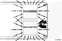
On ISLe4 engines the “MALFUNCTION” or “ENGINE MALFUNCTION” lamp is a blue lamp and indicates that the vehicle may be exceeding emission level limits. When illuminated, the MALFUNCTION or ENGINE MALFUNCTION lamp (blue lamp) indicates the engine or exhaust gas treatment system is need of repair at the first available opportunity.
Another function of the MALFUNCTION or ENGINE MALFUNCTION lamp (blue lamp) is to flash when the urea (commonly referred to as AdBlue™) tank is empty.
Hello, I'm Jack, a diesel engine fan and a blogger. I write about how to fix and improve diesel engines, from cars to trucks to generators. I also review the newest models and innovations in the diesel market. If you are interested in learning more about diesel engines, check out my blog and leave your feedback.
View all posts by Jack


;)
;)
;)
;)
;)
;)
;)
;)
;)
;)
;)
;)
;)
;)
;)
;)
;)
;)
;)
;)