General Information
|
TOC |
|
|
|
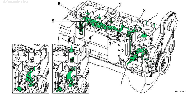
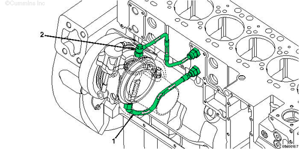
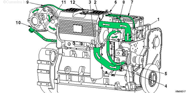
| Internal Engine Coolant Flow, All Applications |
 CAUTION
Never operate the engine without a thermostat. Without a thermostat, the coolant will not flow to the radiator, and the engine will overheat.
|
NOTE: The thermostat flow shown is not for QSL9 keel cooled engines. On QSL9 keel cooled marine engines, the thermostat is located in the keel cooled thermostat housing. See flow diagram below.
- Coolant inlet from radiator
- Water pump suction
- Coolant flow through lubricating oil cooler
- Block lower water manifold (to cylinders)
- Coolant filter inlet (optional)
- Coolant filter outlet (optional)
- Coolant supply to cylinder head
- Coolant return from cylinder head
- Block upper water manifold
- Thermostat bypass
- Coolant return to radiator
- Turbocharger coolant supply
- Turbocharger coolant drain
|
|
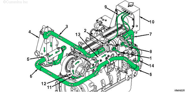
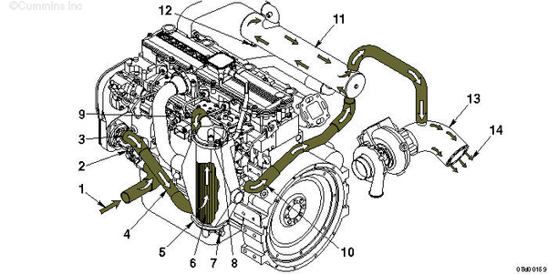
| QSL9 with Keel Cooled (Engine Coolant) |
- Engine coolant return from keel cooler
- Keel cooler thermostat housing
- Engine coolant to aftercooler
- Aftercooler
- Engine coolant through marine gear oil cooler
- Engine coolant to water pump
- Engine discharge to keel cooler thermostat
- Engine coolant to keel cooler
- Cooling system housing vent line
- Expansion tank
- Engine coolant from engine to turbocharger
- Turbocharger turbine housing
- Exhaust manifold
- Engine coolant return from exhaust manifold to water pump.
|
|
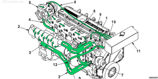
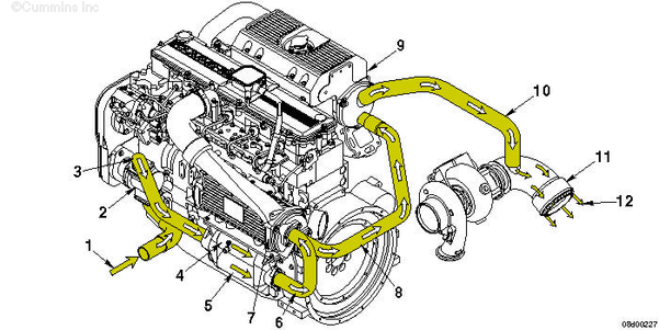
| QSL9 with Heat Exchanger (Engine Coolant) |
- Coolant from thermostat to heat exchanger
- Heat exchanger
- Coolant return from heat exchanger to water pump
- Turbocharger coolant supply from cylinder block
- Turbocharger with water cooled turbine housing
- Water cooled exhaust manifold
- Coolant return from exhaust manifold to water pump
- Turbocharger coolant vent line
- Exhaust manifold coolant vent line
- Cylinder head coolant vent line
- Expansion tank
- Coolant makeup to water pump from expansion tank.
- Coolant from thermostat
- Heat exchanger coolant inlet
- Heat exchanger coolant outlet
- Water pump coolant inlet from heat exchanger
- Water pump coolant inlet from exhaust manifold
- Expansion tank
- Coolant vent line from cylinder head to expansion tank
- Coolant vent line from exhaust manifold to expansion tank
- Coolant vent line from turbocharger to expansion tank
- Turbocharger coolant inlet from cylinder block
- Coolant from turbocharger to exhaust manifold
- Expansion tank fill cap.
|
|
| QSL9 Sea Water Cooled (Heat Exchanger), Marine Applications |
- Sea water pump inlet
- Sea water pump
- Sea water pump discharge to fuel cooler
- Fuel cooler
- Aftercooler sea water inlet
- Aftercooler
- Aftercooler lower zinc anode
- Aftercooler upper zinc anode
- Aftercooler sea water outlet to marine gear oil cooler
- Marine gear oil cooler sea water outlet to heat exchanger
- Heat exchanger
- Heat exchanger zinc anode
- Exhaust elbow
- Sea water discharge.
|
|
| QSC8.3 Sea Water Cooled (Heat Exchanger), Marine Applications |
- Sea water pump inlet
- Sea water pump
- Sea water pump discharge to combination marine gear oil and fuel cooler
- Fuel cooler
- Marine gear oil cooler
- Combination marine gear oil cooler and fuel cooler discharge to aftercooler inlet
- Aftercooler
- Aftercooler discharge to heat exchanger
- Heat exchanger/expansion tank assembly
- Heater exchanger discharge to exhaust elbow
- Exhaust elbow
- Sea water discharge.
|
Last Modified: 07-Dec-2009
Published by Jack
Hello, I'm Jack, a diesel engine fan and a blogger. I write about how to fix and improve diesel engines, from cars to trucks to generators. I also review the newest models and innovations in the diesel market. If you are interested in learning more about diesel engines, check out my blog and leave your feedback.
View all posts by Jack
;)
;)
;)
;)
;)
;)
;)
;)
;)
;)
;)
;)
;)
;)