|
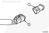
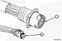
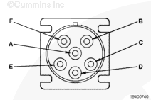
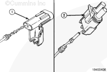
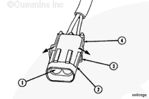
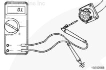
The 3-pin SAE J1939 Deutsch™ connectors are also found on some Cummins® engine harnesses. Two possible types of 3-pin connectors can be present: A 3-pin plug (1), Part Number 3824288; and a 3-pin receptacle (2), Part Number 3824290. The following are the pin-outs for the 3-pin connector:
|
Pin
|
Signal
|
|
A
|
J1939 data link (+)
|
|
B
|
J1939 data link (-)
|
|
C
|
J1939 data link (shield)
|
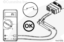
The 3-pin connector only supports the SAE J1939 data link.
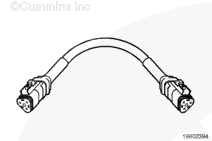
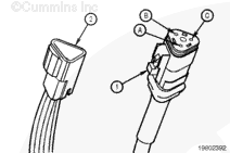
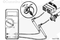
To meet the SAE J1939 standard, the 3-pin receptacle connector must be within 0.66 m [2.16 ft] of the ECM. Use of the J1939 mini-backbone harness, Part Number 3163096; may be required for proper termination resistance. The mini-backbone harness is required when no backbone is provided on the data link. Gender changer cable, Part Number 3163597, may be required to connect the mini-backbone harness to the engine harness or service tool cable.
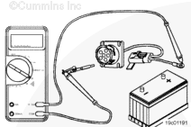
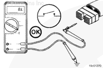
NOTE: If there is 60 ohm resistance measured between pins A and B of the 3-pin connector, a backbone is on the data link.
On an ISB (except in a Dodge Ram™ pickup truck), an ISC, or an ISL engine, the 3-pin receptacle connector is located approximately six inches from the ECM.
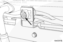
On an ISB in a Dodge Ram™ pickup truck, the 3-pin plug connector is located near the fuel pump on the front gear housing.
On an ISM or ISX engine (prior to October 2002) the 3-pin receptacle is an OEM option. If the OEM has supplied a 3-pin receptacle connector, Part Number 3824290, for communications, it will be located in the OEM harness within 0.66 m [2.16 ft] of the ECM.
On an ISM or ISX engine (after October 2002) the 3-pin receptacle is located on the cold side of the engine.
On B Gas PLus, B LPG Plus, and C Gas Plus engines, the 3-pin SAE J1939 Deutsch™ receptacle, Part Number 3824290 is located near the OEM interface connectors. This connector is the OEM connection point for SAE J1939 devices and can also be used for INSITE™ electronic service tool communication. A mini-backbone harness, Part Number 3163096, is required for direct INSITE™ electronic service tool communication.
|


 WARNING
  CAUTION
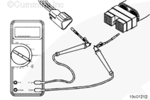
;)
;)
;)
;)
;)
;)
;)
;)
;)
;)
;)
;)
;)
;)
;)
;)
;)
;)
;)
;)
;)
;)
;)
;)
;)
;)
;)
;)
;)
;)
;)
;)
;)
;)