The leads must fit tightly in the connector without expanding the pins in the connector otherwise the connector will be damaged.
NOTE: The idle/diagnostic increment/decrement switch is the cruise control/PTO/set/resume select switch.
If INSITE™ electronic service tool is available, monitor the idle adjust switch circuit for proper operation. If not, follow the troubleshooting procedures in this section.
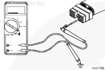
Remove the original equipment manufacturer (OEM) harness connector from the electronic control module (ECM).
Insert the pin of the test lead into the cruise control/PTO set/coast switch signal in the OEM harness connector. Measure the resistance from the cruise control/PTO set/coast switch signal to the engine block.
Hold the idle adjust switch in the positive (+) increment position.
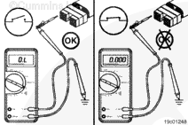
If the OEM connected the return wire to chassis ground the multimeter must show a closed circuit (10 ohms or less) while holding the switch on and return to an open circuit (100K ohms or more) when the switch is released. The circuit must remain an open circuit when the switch is in the decrement negative (-) position.
If the OEM connected the return wire to the ECM OEM connector the multimeter must show an open circuit (100k ohms or more) while holding the switch on and return to a closed circuit (10 ohms or less) when the switch is released. The circuit must remain a closed circuit when the switch is in the decrement negative (-) position.
If the resistance values are not correct, make sure the return wire and the cruise control/PTO set/coast switch signal wire are properly installed on the idle adjust switch. If both wires are correctly installed, inspect the return wire and the cruise control/PTO set/coast switch signal wire for open circuits, provided the idle adjust switch has been previously checked for short circuits to ground.
Remove the lead from the cruise control/PTO set/coast switch signal and insert it into the cruise control/PTO resume/accelerator switch signal.
Hold the idle adjust switch in the negative (-) decrement position. The multimeter must show a closed circuit (10 ohms or less) when the switch is held in the decrement position and an open circuit (100K ohms or more) when the switch is released. The circuit must remain an open circuit when the switch is in the positive (+) increment position.
If the resistance values are not correct, make sure the cruise control/PTO resume/accelerator switch signal wire is properly installed on the idle adjust switch. If the cruise control/PTO resume/accelerator switch signal wire is properly installed on the idle adjust switch, inspect the cruise control/PTO resume/accelerator switch signal wire for an open circuit, provided the idle adjust switch has been previously checked for short circuits to ground.
The multimeter must show an open circuit (100K ohms or more). If the circuit is not open, there is a short circuit to ground in the cruise control/PTO resume/accelerator switch signal circuit, provided the idle adjust switch has been previously checked.
Repair or replace the wire connected to the cruise control/PTO resume/accelerator switch signal in the OEM harness according to the vehicle manufacturer’s instructions.
To check the idle/diagnostic increment wire (attached the to cruise control/PTO set/coast switch signal) for short circuits to ground, follow the same procedure as described above for the idle/diagnostic decrement wire.
Measure the resistance from the cruise control/PTO resume/accelerator switch signal of the OEM harness connector to all other pins in the connector. The multimeter must show an open circuit (100k ohms or more).
If the circuit is not open, there is a short circuit between the wire connected to the cruise control/PTO resume/accelerator switch signal and any pin that measured less than 100k ohms.
Repair or replace the wires in the OEM harness according to the vehicle manufacturer’s instructions.
Remove the lead from the cruise control/PTO resume/accelerator switch signal of the OEM harness connector and insert it into the cruise control/PTO set/coast switch signal of the connector. Measure the resistance from the cruise control/PTO set/coast switch signal to all other pins in the connector. The multimeter must show an open circuit (100k ohms or more).
If the circuit is not open, there is a short circuit between the wire connected to the cruise control/PTO set/coast switch signal and any pin that measured less than 100k ohms, provided the idle adjust switch has been previously checked.
Repair or replace the wires in the OEM harness according to the vehicle manufacturer’s instructions.
Connect all components after completing the repair.
Hello, I'm Jack, a diesel engine fan and a blogger. I write about how to fix and improve diesel engines, from cars to trucks to generators. I also review the newest models and innovations in the diesel market. If you are interested in learning more about diesel engines, check out my blog and leave your feedback.
View all posts by Jack

 CAUTION


;)
;)
;)
;)
;)
;)
;)
;)
;)
;)
;)
;)