 WARNING
Batteries can emit explosive gases. To reduce the possibility of personal injury, always ventilate the compartment before servicing the batteries. To reduce the possibility of arcing, remove the negative (-) battery cable first and attach the negative (-) battery cable last.
|
 CAUTION
The leads must fit tightly in the connector without expanding the pins in the connector otherwise the connector will be damaged.
|
Disconnect the batteries.
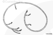
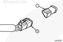
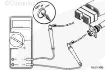
Disconnect the OEM harness connector from the ECM. Turn the keyswitch to the OFF position.
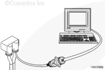
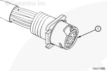
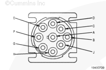
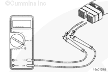
Insert a test lead into the SAE J1939 datalink positive (+) pin of the OEM harness connector, and connect it to the multimeter probe. Insert the other test lead into the SAE J1939 datalink positive (+) pin of the 9-pin Deutsch™ connector, and connect it to the multimeter.
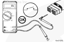
Measure the resistance. The multimeter
must show a closed circuit (10 ohms or less).
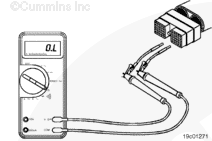
If the circuit is
not closed, repair or replace the OEM harness. Refer to the OEM troubleshooting and repair manual for the procedures.
Insert the multimeter lead into the SAE J1939 datalink negative (-) of the OEM harness connector. Touch the other lead to the SAE J1939 datalink negative (-) pin of the 9-pin Deutsch™ connector. Measure the resistance. The multimeter
must show a closed circuit (10 ohms or less)
If the circuit is
not closed, repair or replace the OEM harness. Refer to the OEM troubleshooting and repair manual for the procedures.
If the values are correct, the circuit
must still be checked for a short circuit to ground and a short circuit from pin to pin.
Remove the lead from the SAE J1939 datalink negative (-) pin of the OEM harness connector and insert it into the SAE J1939 datalink (shield) pin, if the shield pin is available.
If the J1939 datalink circuit is an unshielded twisted pair (UTP), the shield pin will
not be provided.
If the shield pin is provided, measure the resistance from the SAE J1939 datalink (shield) pin of the OEM harness connector to the SAE J1939 datalink (shield) pin of the 9-pin Deutsch™ connector.
The multimeter
must show a closed circuit (10 ohms or less). If the circuit is
not closed, repair or replace the OEM harness. Refer to the OEM troubleshooting and repair manual for the procedures.
If the (shield) pin is provided, measure the resistance from the SAE J1939 datalink (shield) pin of the 9-pin Deutsch™ connector to the engine block ground. The SAE J1939 datalink shield
must be grounded to the vehicle battery ground. The multimeter
must show a closed circuit (10 ohms or less). If the circuit is
not closed, refer to the OEM troubleshooting and repair manual for repair instruction.
If more than 10 ohms are measured in any of these steps, there can be an open circuit in the SAE J1939 datalink positive (+) pin, the SAE J1939 datalink negative (-) pin, or the SAE J1939 (shield) pin, or the polarity is
not correct. There can also be an open circuit from the datalink (shield) pin to vehicle battery ground.
If the values are correct, the SAE J1939 datalink positive (+) pin and the datalink negative (-) pin
must still be checked for a short circuit to ground. The SAE J1939 datalink positive (+) pin, the datalink negative (-) pin, and the datalink (shield) pin
must still be checked for a short circuit from pin to pin.
|


;)
;)
;)
;)
;)
;)
;)
;)
;)
;)
;)
;)
;)
;)
;)
;)
;)
;)