 CAUTION
The leads must fit tightly in the connector without expanding the pins in the connector otherwise the connector will be damaged.
|
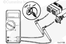
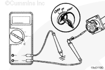
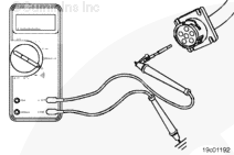
Turn the keyswitch to the ON position. Adjust the multimeter to measure VDC.
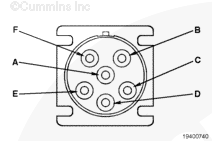
Insert a test lead into the SAE J1587 datalink positive (+) pin of the 6-pin connector and connect it to a multimeter probe. Touch the other multimeter probe to the engine block ground. Measure the voltage.
The multimeter
must read 3.5 to 5 VDC for the voltage check from the SAE J1587 datalink positive (+) pin of the datalink connector to ground.
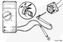
Remove the test lead from the SAE J1587 datalink positive (+) pin and insert it into the SAE J1587 datalink negative (-) pin of the 6-pin Deutsch connector. Touch the other multimeter probe to the engine block ground. Measure the voltage.
The multimeter
must read 0 to 2.5 VDC for the voltage check from the SAE J1587 datalink negative (-) pin of the datalink connector to ground.
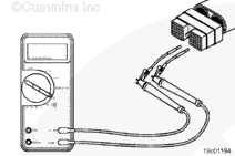
Remove the test lead from the SAE J1587 datalink negative (-) pin and insert it into battery positive (+) pin of the 6-pin connector. Touch the other multimeter probe to the engine block ground. Measure the voltage.
The multimeter
must read battery voltage for the voltage check from pin C of the datalink connector to ground.
Remove the test lead from the battery positive (+) pin and insert it into the battery negative (-) pin of the 6-pin connector. Touch the other multimeter probe to the engine block ground. Measure the voltage.
The multimeter
must read 0 voltage for the voltage check from the battery negative (-) pin of the datalink connector to ground.
|


 WARNING
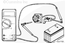

;)
;)
;)
;)
;)
;)
;)
;)
;)
;)
;)
;)
;)
;)
;)
;)