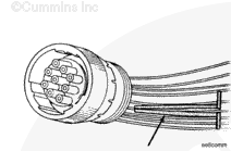
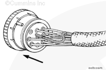
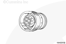
These connectors are available with multiple pin configurations.
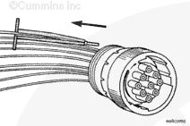
Refer to the appropriate wiring repair kit in the service tools table in the front of Section 19 for the correct repair wire. Replace one contact at a time. If more than one wire needs replaced, attach a lettered tag to each wire removed.
Refer to the wiring diagram in Section E for pin locations.
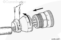
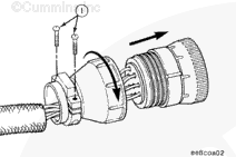
Unlock the connector. Rotate the locking tab counterclockwise by hand. Do not use pliers; they can damage the connector.
Remove the two clamp capscrews (1) from the rear of the connector. Turn the rear support of the connector counterclockwise until the two pieces are separated.
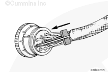
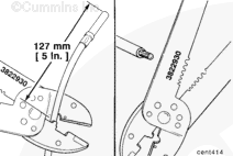
Hold the tool on the terminal flange and pull the wire and the connecting pin out of the connector. Note and record the hole from which the pin is removed.
Hold the tool on the terminal flange and pull the wire and the connecting pin out of the connector. Note and record the hole from which the pin is removed.
Hello, I'm Jack, a diesel engine fan and a blogger. I write about how to fix and improve diesel engines, from cars to trucks to generators. I also review the newest models and innovations in the diesel market. If you are interested in learning more about diesel engines, check out my blog and leave your feedback.
View all posts by Jack


;)
;)
;)
;)
;)
;)
;)
;)
;)
;)
;)
;)
;)
;)
;)
;)
;)
;)
;)
;)