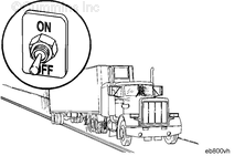
The fan control switch circuit signals the system that the operator is requesting the engine fan to be engaged. The fan on and off circuit consists of the fan control switch signal, the switch return, and the OEM cab-mounted toggle switch. This circuit is considered “fail safe”, meaning when the circuit is open, the engine fan will be engaged by the ECM.
NOTE: This procedure is only valid if the fan control switch is wired through the ECM and the feature manual fan switch is enabled in the ECM. If the fan control switch is wired in series with the fan control relay, the ECM could log fan circuit errors during normal operation. Please verify the circuit is wired properly before performing this procedure.
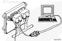
If INSITE™ is available, monitor the fan control switch for proper operation. If not operating properly, follow the troubleshooting procedures in this section.
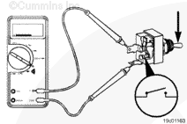
Locate the fan control switch. Label the wires with the location of the switch or the wire number. Remove the electrical connectors from the switch. Adjust the multimeter to measure resistance. Touch one multimeter probe to one of the terminals on the switch. Touch the other multimeter probe to the other terminal of the switch.
Move the switch to the ON position and measure the resistance. The multimeter must show an open circuit (100k ohms or more). If the circuit is not open, the switch has failed. Refer to the OEM troubleshooting and repair manual for replacement procedures.
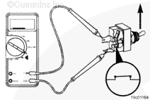
Place the switch in the OFF position and measure the resistance. The multimeter must show a closed circuit (10 ohms or less). If the circuit is not closed, the switch has failed. Refer to the OEM troubleshooting and repair manual for replacement procedures. If the resistance value is correct, the switch must still be checked for a short circuit to ground.
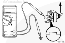
Touch one of the multimeter probes to one of the switch terminals. Touch the other probe to chassis ground. Move the switch to the OFF position and measure the resistance. The multimeter must show an open circuit (100k ohms or more). If the circuit is not open, the switch has failed. Refer to the OEM troubleshooting and repair manual for replacement procedures. If the switch passes all of the previous checks, the circuit must be checked for an open circuit, a short circuit to ground, a short circuit from pin to pin, and a short circuit to an external voltage source.
Hello, I'm Jack, a diesel engine fan and a blogger. I write about how to fix and improve diesel engines, from cars to trucks to generators. I also review the newest models and innovations in the diesel market. If you are interested in learning more about diesel engines, check out my blog and leave your feedback.
View all posts by Jack


;)
;)
;)
;)
;)
;)
;)
;)
;)
;)