The cylinder case has five bores to support the camshaft. The bores use one-piece sleeve bearings of different sizes, with bores #1 to #4 having a larger inside diameter than bore #5.
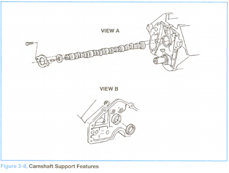
A thrust plate mounted at the front of the cylinder case controls the camshaft end-play (see Figure 2-8, view A). A spacer positioned between the camshaft and thrust washer is installed with a chamfer on its inner diameter facing the camshaft.
A cup plug at the rear of the cylinder case seals camshaft bore #5 (see Figure 2-8, view B). A sealant is used on the outside diameter of the plug, which is installed flush with its bore.
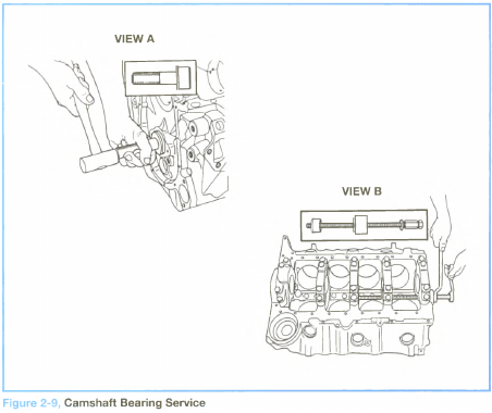
During service, camshaft bearings #1 and #5 may be removed and installed by using a special driver (see Figure 2-9, view A). The removal and installation of bearings #2, #3 and #4 require the use of a special pulling tool (see Figure 2-9, view B).
To assure proper oiling and support for camshaft loads during engine operation, the camshaft bearings installed during service must have the following alignment features:
• An oil supply hole of each bearing must be in the 4 o’clock position (when viewed from the front of the engine).
• The seam of each bearing must face the upper part of the engine.
• The #1 bearing has a notch that faces the front of the engine, as well as another oil hole positioned in the 12 o ’clock position.