Construction and Operation
Each cylinder has an identical fuel injection nozzle mounted in the pre-combustion chamber, using threads and a copper sealing gasket. A specific injection line connects to each nozzle, using a special fitting and nut.
Each nozzle is an assembly containing a two-piece body, a needle valve/pintle nozzle assembly, a pressure spring and other parts (see Figure 7-55). During the manufacturing process, a selective thickness shim is used to adjust the nozzle opening pressure .

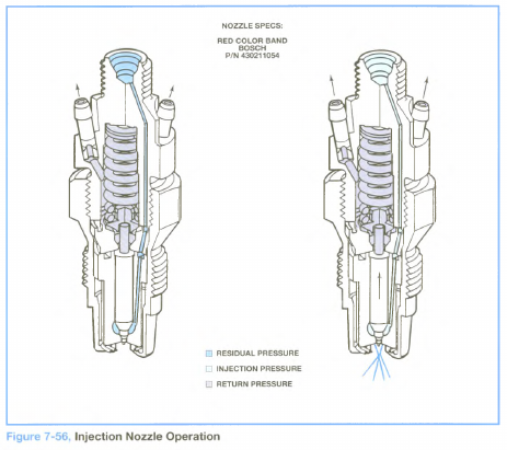
As the pressure wave of injection reaches a nozzle, the needle valve is lifted against spring force and fuel exits into the pre-combustion chamber of the cylinder as a highly atomized spray (refer to Figure 7-56). A small amount of fuel travels between the needle valve and pintle nozzle, providing lubrication.
Two passages inside the upper half of the nozzle body allow fuel that has lubricated the needle valve to exit into the fuel return system. Fittings on the nozzle connect with hoses and clamps to the return system pipes.
During service, nozzles are serviced by replacement. Installation involves the use of a new compression gasket, anti-seize compound (GM P/N 1052771) on the cylinder head threads and a tightening torque of 60 to 80 N-m (44 to 59 Ib-ft), using a special socket.
Injection Nozzle Testing
During diagnosis, each injection nozzle may be tested after it is removed from the engine (refer to page 7-53). Nozzle tests include the following checks:
1. Preparation
• Position a nozzle tester on a workbench.
• Install one nozzle on the tester fitting.
• Place a container under the nozzle that will deflect the nozzle spray and absorb the test fluid.
• Install two clear plastic hoses (11/2in. long) over the leak-off fittings.
• Close the shut-off valve at the pressure gauge.
• Operate the lever of the nozzle tester repeatedly and briskly to fill and flush the nozzle with test oil.
Note: Never allow the nozzle spray to contact your hands, since it can penetrate the skin and cause blood poisoning.
2. Opening pressure check:
• Open the shut-off valve at the pressure gauge 1/4-turn.
• Push the lever of the tester to increase pressure slowly.
• Observe the pressure gauge at the point which the nozzle sprays, and note the reading as the opening pressure.
Note: Do not consider dripping at the nozzle during this check as a fault.
• Compare the reading to the specification 120 bar (1750 psi), and replace the nozzle if the opening pressure is below this point.
3. Leakage check:
• Open the shut-off valve at the pressure gauge 1/2 to 11/2turns.
• Dry the nozzle tip with air.
• Push the lever of the tester to increase pressure to 95 bar (1400 psi).
• Observe the tip of the nozzle for drops of test oil.
• If a drop falls from the nozzle tip within 10 seconds, replace the nozzle.
4. Chatter check:
• Close the shut-off valve at the pressure gauge.
• Push the lever at a speed that causes the nozzle to chatter as it sprays repeatedly.
• If chatter is not heard, push the lever at a faster speed.
• If no chatter is heard, replace the nozzle.
Note: New and used nozzles have different sound characteristics during the chatter check.
5. Spray pattern check:
• Close the shut-off valve at the pressure gauge.
• Push the lever of the tester abruptly and quickly.
• Observe the spray pattern of the nozzle:
– Do not be too critical of the spray pattern since it is not tested properly with this check.