This component or assembly weighs greater than 23 kg [50 lb]. To prevent serious personal injury, be sure to have assistance or use appropriate lifting equipment to lift this component or assembly.
CAUTION
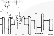
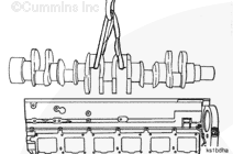
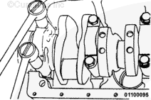
Use a lifting strap that will not damage the crankshaft. Do not drop the crankshaft on the bearings.
The end of the crankshaft with the smallest diameter must point toward the front of the block. Install the crankshaft.
NOTE: If used thrust bearings are to be installed, each must be installed in its original location in the engine. The bearing journal numbers must have been marked on the bearing during disassembly.
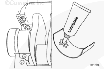
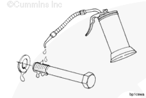
Use clean Lubriplate™ 105, or equivalent, to lubricate the upper thrust bearings.
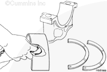
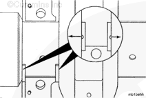
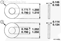
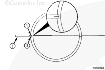
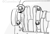
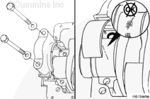
Do not intermix the main bearing dowel ring and the main bearing capscrew washers. The hardened main bearing capscrew washer (1) is approximately 0.76 mm [0.030 in] thicker than the soft main bearing dowel ring (2). Intermixing the capscrew washers and the dowel rings will result in main bearing failure.
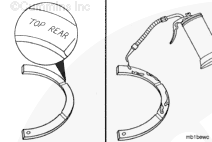
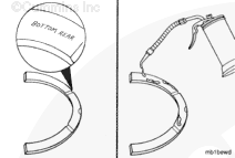
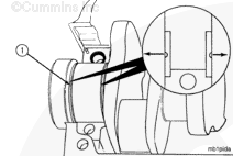
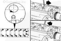
The end of the lower main bearing shell opposite the dowel ring must be engaged between the crankshaft and the cylinder block and be seated against the end of the upper bearing shell.
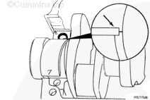
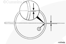
NOTE: If installed correctly, the ends of the bearing shells (1) will meet approximately 1.50 mm [0.060 in] below the cylinder block main bearing mounting surface.
NOTE: If used thrust bearings are to be installed, each must be installed in its original location in the engine. The bearing journal numbers must have been marked on the bearing during disassembly.
Use Lubriplate® 105, or equivalent, to lubricate the lower thrust bearings.
Drain the excess oil from the capscrews before installing them in the cylinder block to prevent hydraulic lock and possible damage to the cylinder block during the capscrew torquing operation.
Use clean 15W-40 oil to lubricate the capscrew threads and flat washers.
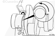
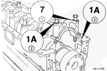
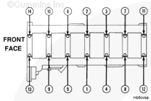
The main bearing caps are marked for position (1) on the camshaft side and the cylinder block identification (2) on the exhaust side. The cylinder block identification number (3) is stamped on the pan rail on the camshaft side of the block. Install the caps in the correct position with the position number to the camshaft side and its part number toward the rear of the engine.
Install the main bearing caps as follows:
Align the capscrew holes in the cap with the holes in the cylinder block. Make sure the dowel ring and lower bearing shell are in position.
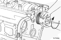
Turn the crankshaft by hand. If it does not turn freely, loosen the main bearing capscrews one cap at a time. This will help locate the bearing that is too tight.
Remove the main bearing cap and the bearing. Check for an incorrect or mislocated bearing or main bearing cap, for incorrect oversize bearing, or debris between the main bearing and the cap.
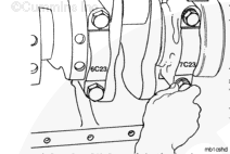
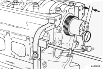
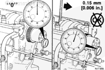
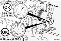
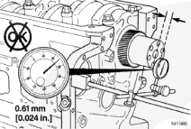
Measure the crankshaft end clearance. The end clearance specification for a new or reground crankshaft with new thrust bearings is 0.18 mm [0.007 in] to 0.45 mm [0.018 in].
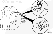
NOTE: Crankshafts that have been reground on the thrust bearing surfaces are marked for oversize thrust bearings on the rear crankshaft counter weight. If the crankshaft counter weight is marked, check the thrust ring part number to make sure the correct thrust ring size is used.
If the crankshaft end clearance is more than 0.56 mm [0.022 in], use oversize thrust bearings to adjust the end clearance to the correct specification.
Hello, I'm Jack, a diesel engine fan and a blogger. I write about how to fix and improve diesel engines, from cars to trucks to generators. I also review the newest models and innovations in the diesel market. If you are interested in learning more about diesel engines, check out my blog and leave your feedback.
View all posts by Jack


 WARNING
  CAUTION


;)
;)
;)
;)
;)
;)
;)
;)
;)
;)
;)
;)
;)
;)
;)
;)
;)
;)
;)
;)
;)
;)
;)
;)
;)
;)
;)
;)
;)
;)
;)
;)
;)
;)
;)
;)
;)
;)
;)
;)
;)
;)
;)
;)
;)
;)
;)
;)
;)
;)
;)
;)
;)
;)