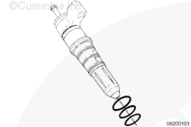
When installing injectors for reuse, new o-rings must be installed on the injector.
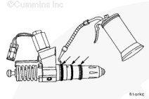
NOTE: The CELECT™ Plus injectors require three different injector o-rings. The traditional black, brown, and black with white dot colors have been changed to red, white, and blue respectively. The coloring is a Teflon® casting; the o-ring material has not been changed. There is no change in part numbers for these o-rings. The old colors will be present until existing stock is depleted. It is okay to mix the black and the red o-ring, the brown and the white o-ring, or the black with the white dot and blue o-ring.
Top – red
Middle – white
Bottom – blue.
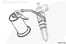
Lubricate the o-rings with lubricating oil just before installation.
To reduce the possibility of injector damage, do not strike the top stop spring cage when installing CELECT™ Plus injectors.
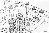
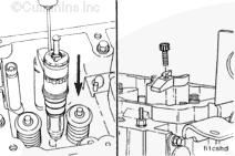
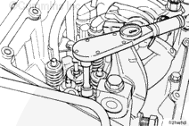
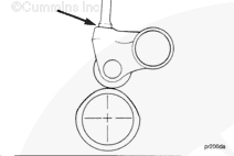
Use the CELECT™ Plus injector puller/installer, Part Number 3823579, to install the injector into the cylinder head injector bore with the injector solenoid valve facing the intake side of the engine.
Do not strike or pry on the solenoid. Otherwise, injector damage will occur.
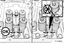
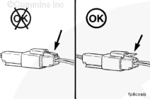
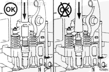
After partial installation of the injector, take precautions to center the solenoid valve between the valve springs. Avoid contact with the spring coils. If the injector is contacting a valve spring, use a screwdriver to position the injector again.
Continue driving the injector into the bore, use the injector puller/installer, Part Number 3823579.
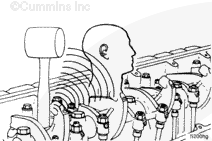
If an injector puller/installer, Part Number 3823579, is not available, a screwdriver can be used to install the injector by putting the screwdriver on the injector body at the base of the injector solenoid and striking the screwdriver with a soft mallet. Do not strike on the injector solenoid or on the top stop spring cage.
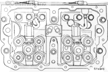
The injector must be fully seated before installing the hold-down clamp. The hold-down clamp can not pull the injector into the bore. Engine damage can occur if the injector is not fully seated.
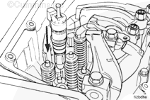
Install a set of new injectors, use the 8-qt 10-hole cup configuration that was removed from the engine. This will make sure the injectors will not have any unseen cavitation damage internal to the injector cup at the time of kit installation.
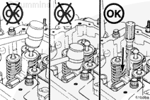
Make sure to place the instrument used to install the injectors on the top cap of the injector, not on the plunger or link. The plungers will be damaged.
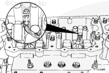
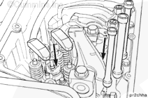
Install a 27 mm [1-1/16 in] deep well socket over the top link of the injector. The socket must rest completely on the top surface of the injector top cap to avoid bending the inner part of the top cap.
Use a clean, blunt instrument to seat the injector in the bore.
The injector must be fully seated before installing the hold-down clamp. The hold-down clamp can not pull the injector into the bore. Engine damage can occur if the injector is not fully seated.
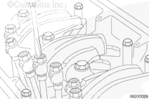
Install the injector hold-down clamp and capscrew.
Hello, I'm Jack, a diesel engine fan and a blogger. I write about how to fix and improve diesel engines, from cars to trucks to generators. I also review the newest models and innovations in the diesel market. If you are interested in learning more about diesel engines, check out my blog and leave your feedback.
View all posts by Jack


 CAUTION
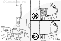


;)
;)
;)
;)
;)
;)
;)
;)
;)
;)
;)
;)
;)
;)
;)
;)
;)
;)
;)
;)
;)
;)
;)
;)
;)
;)
;)
;)
;)
;)
;)
;)
;)
;)
;)
;)
;)
;)