Batteries can emit explosive gases. To reduce the possibility of personal injury, always ventilate the compartment before servicing the batteries. To reduce the possibility of arcing, remove the negative (-) battery cable first and attach the negative (-) battery cable last.
WARNING
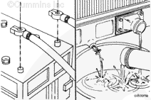
Coolant is toxic. Keep away from children and pets. If not reused, dispose of in accordance with local environmental regulations.
Disconnect the batteries. Refer to the OEM service manual.
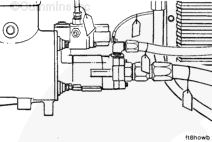
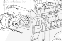
Disconnect the starting motor cable, the engine ground straps, the cab or chassis to engine hoses, the tubing, the electrical wires, and the hydraulic lines.
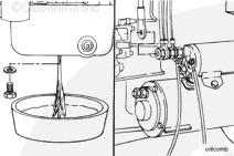
NOTE: Dispose of used oil in accordance with federal, state, and local laws and regulations.
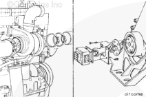
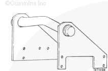
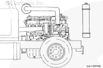
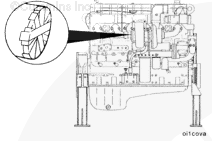
In installations such as short and medium nose conventional chassis, the factory installed rear engine lifting bracket is usually removed due to space constraints. In this case, the service rear engine lifting bracket, Part Number 3823920, will be required to remove the engine from the chassis.
The service rear engine lifting bracket, Part Number 3823920, consists of the bracket and eight 3/8-16×1-inch UNC (Grade 8) mounting capscrews and flat washers.
Use the following steps to install the service rear engine lifting bracket.
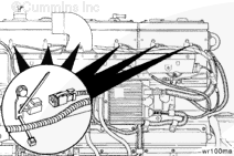
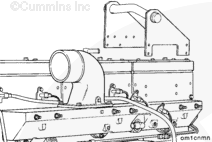
Position the service lifting bracket, Part Number 3823920, over the rear rocker lever housing being careful not
to damage the injector wiring rocker lever housing pass through connectors.
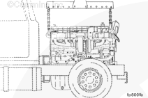
Attach the left plate of the lifting bracket to the fuel pump side of the rear rocker lever housing. Install the four 3/8-16×1-inch UNC (Grade 8) mounting capscrews and washers.
Torque Value: 75 n.m [55 ft-lb]
CAUTION
If all fasteners are not installed and tightened to the correct torque value, the lifting bracket will malfunction. Severe engine damage and personal injury are possible.
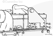
Attach the right plate of the lifting bracket to the exhaust side of the rear rocker lever housing. Install the four 3/8-16×1-inch UNC (Grade 8) mounting capscrews and washers.
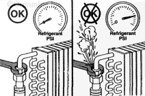
If a liquid refrigerant system (air conditioning) is used, wear eye and face protection and wrap a cloth around the fittings before removal. Liquid refrigerant can cause serious eye and skin injury.
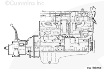
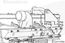
The engine lifting equipment must be designed to safely lift the engine and the transmission as an assembly. The dry weight of the standard engine with accessories is 1256 kg [2770 lbs]. Refer to the equipment manufacturer’s specifications for the transmission weight.
Use a correctly rated hoist; and attach engine lifting fixture, Part Number ST-125 or Part Number 3822512, to the engine mounted lifting brackets to remove the engine.
NOTE: If the transmission is
not
removed, place a support under the transmission to prevent it from falling.
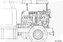
Engines with stamped steel rocker lever covers require removal of the number 3 (rear) cover.
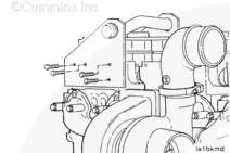
Position the service lifting bracket, Part Number 3823920, over the rear rocker lever housing, being careful not
to damage the CELECT™ injector wiring rocker lever housing pass through connector.
If all fasteners are not installed and tightened to the correct torque value, the lifting bracket will fail. Severe engine damage and personal injury are possible.
Attach the lifting bracket to the fuel pump side of the rear rocker lever housing. Install the 3/8 – 16 X 1-inch UNC (Grade 8) mounting capscrews and washers into the rocker lever housing.
Attach the right plate of the lifting bracket to the exhaust side of the rear rocker lever housing. Install the 3/8 – 16 X 1-inch UNC (Grade 8) mounting capscrews and washers into the rocker lever housing.
Torque Value: 75 n.m [55 ft-lb]
CAUTION
If all fasteners are not installed and tightened to the correct torque value, the lifting bracket will fail. Severe engine damage and personal injury are possible.
Hello, I'm Jack, a diesel engine fan and a blogger. I write about how to fix and improve diesel engines, from cars to trucks to generators. I also review the newest models and innovations in the diesel market. If you are interested in learning more about diesel engines, check out my blog and leave your feedback.
View all posts by Jack

 WARNING

 CAUTION

;)
;)
;)
;)
;)
;)
;)
;)
;)
;)
;)
;)
;)
;)
;)
;)
;)
;)
;)
;)
;)
;)
;)
;)
;)
;)
;)
;)
;)
;)
;)
;)
;)
;)
;)
;)