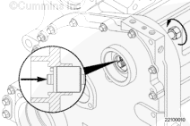
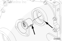
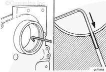
In order to correctly align the oil hole in the bushing with the hole in the gear cover, scribe a line on the outside diameter and face of the bushing, centered through the oil hole.
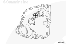
Scribe another line on the face of the gear cover, centered through the oil hole.
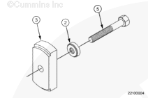
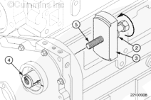
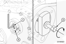
Position the bushing driver plate (3), thrust bearing (2), and the accessory drive forcing screw (5) over the block face where the accessory drive is mounted.
Rotate the accessory drive forcing screw (5) clockwise in the bushing driver mandrel (4).
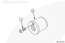
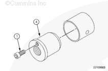
Insert a 1/4-inch Allen wrench in the capscrew (1) to keep the bushing driver mandrel (4) from rotating when turning the accessory drive forcing screw (5).
Turn the accessory drive forcing screw (5) clockwise while holding the bushing driver mandrel (4).
Position the bushing driver plate (3), thrust bearing (2), and the accessory drive forcing screw (5) over the block face where the accessory drive is mounted.
Rotate the accessory drive forcing screw (5) clockwise into the bushing driver mandrel (4).
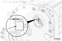
NOTE: Make sure the scribe line on the bushing stays aligned with the scribe line on the face of the gear cover.
NOTE: Make sure the scribe line on the bushing stays aligned with the scribe line on the face of the gear cover.
Insert a 1/4-inch Allen wrench in the capscrew (1) to keep the bushing driver mandrel (4) from rotating when turning the accessory drive forcing screw (5).
Turn the accessory drive forcing screw (5) clockwise while holding the bushing driver mandrel (4).
Hello, I'm Jack, a diesel engine fan and a blogger. I write about how to fix and improve diesel engines, from cars to trucks to generators. I also review the newest models and innovations in the diesel market. If you are interested in learning more about diesel engines, check out my blog and leave your feedback.
View all posts by Jack


 CAUTION
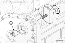

;)
;)
;)
;)
;)
;)
;)
;)
;)
;)
;)
;)
;)
;)
;)
;)
;)
;)
;)
;)
;)
;)
;)
;)