NOTE: Make sure the cylinder block and all parts are clean before assembly. If used liners are being installed again, any sealing rings removed must be installed with the same liner in the same cylinder.
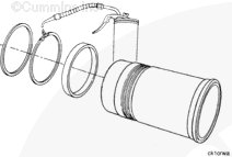
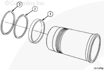
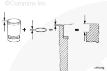
Use vegetable oil to lubricate the new liner o-rings and the crevice seals.
Use vegetable oil to lubricate the o-rings.
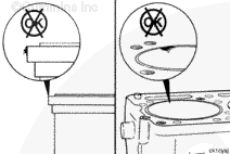
NOTE: Do not use lubricating oil on the o-rings. The o-rings will increase in size after they have been lubricated with oil.
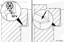
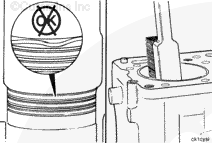
Do not get excessive oil on the counterbore or the liner flange. Excessive oil can result in a hydraulic lock condition and generate inaccurate liner protrusion. Make sure that the o-rings do not move from the grooves.
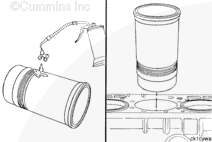
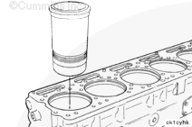
Lubricate the crevice seal and the o-rings with vegetable oil. Install the liner in the bore with a quick push.
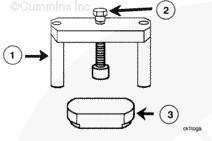
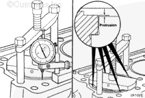
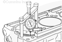
Use liner installation tool, Part Number 3823615, to press the cylinder liner into the cylinder block. Protrusion can be checked while the liner is held down by the installation tool.
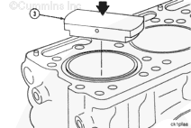
Place the force plate (3) across the top of the liner with the step in the liner bore. Tap the top of the force plate with a soft hammer to square up and start the liner into the press fit bore.
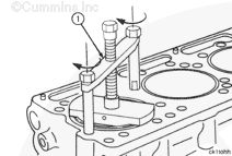
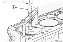
Place the installation tool bridge (1) across the liner and install the two cylinder head capscrews finger tight to hold the bridge down. Rotate the force plate until the areas where the protrusion measurements will be taken are exposed.
Hello, I'm Jack, a diesel engine fan and a blogger. I write about how to fix and improve diesel engines, from cars to trucks to generators. I also review the newest models and innovations in the diesel market. If you are interested in learning more about diesel engines, check out my blog and leave your feedback.
View all posts by Jack


 CAUTION


;)
;)
;)
;)
;)
;)
;)
;)
;)
;)
;)
;)
;)
;)
;)
;)
;)
;)
;)
;)
;)
;)
;)
;)
;)
;)
;)
;)