Notice: Do not allow the RTV sealant into the valve rocker arm cover bolt holes. This may cause a “valve lock” condition, when the bolts are tightened, damaging the cylinder head casting .
1. Apply a 5 m m (3/16 inch) bead of RTV sealant GM P/N 12345739 to the valve rocker arm cover, in board of the bolt holes. The sealer must be wet to the touch when the bolts are tighten.
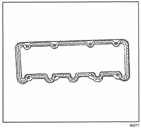
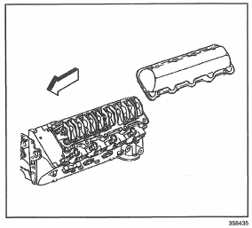
2. Install the valve rocker arm cover to the cylinder head.
Notice: Refer to Fastener Notice in Caution and Notices.
3. Install the valve rocker arm cover bolts to the cylinder head .
Tighten
Tighten the bolts to 22 N-m (16 Ib ft).
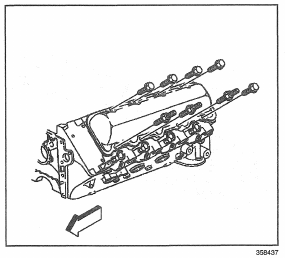
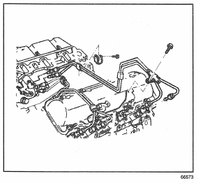
4. Install the fuel injection lines to the fuel injection pump and fuel injectors. Refer to Injection Line(s) Replacement in Engine Controls-6.5L.
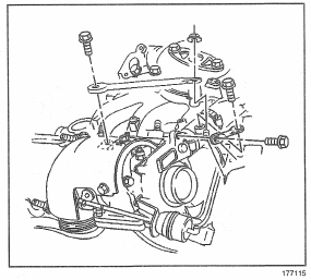
5. Install the lower intake manifold on the cylinder h e a d s . Refer to Intake Manifold Replacement (Lower).
6. Install the heater hose to heater core inlet. Refer to Heater Hoses Replacement in HVAC.
7. Install the rear heater hose to the connector if the vehicle is equipped with rear heat. Refer to Heater Hoses Replacement – Auxiliary (Suburban-Front) in HVAC.
8. Install the engine wiring harness to the right rear or the lower intake manifold (if installing the rights ide valve rocker arm cover only).
9. Install the engine wiring harness to the left of the lower intake manifold (if installing the left side valve rocker arm cover only).
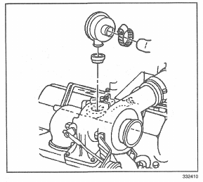
10. Install the CDR valve to the valve rocker arm cover.
11. Install the heat shield to the turbo charger. Refer to Turbocharger Replacement
12. Install the upper intake manifold to the lower intake manifold (L 56 shown). Refer to Intake Manifold Replacement (Upper).
13. Install the oil level indicator and tube. Refer to Oil Level Indicator and Tube Replacement
14. Install the braces to the turbo charger. Refer to Turbocharger Replacement
15. Connect both the battery negative cables to the batteries. Refer to Battery Cable m Engine Electrical.