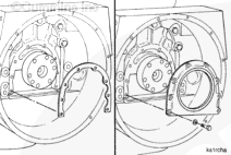
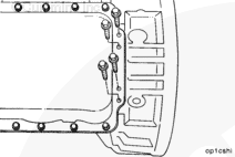
Trim the excess gasket material from the ends of the rear cover gasket so the gasket is even with or does not extend more than 0.25 mm [0.010 inch] beyond the pan flange.
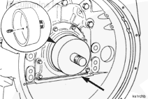
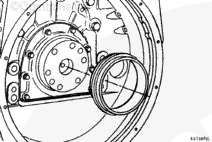
Install the pins into the crankshaft oil seal driver, Part Number 4919705.
Use a dead blow hammer, or two capscrews, Part Number S-162-B, to install the seal until the installer is positioned against the end of the crankshaft. Make sure the seal is perpendicular to the crankshaft during installation.
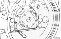
Adjusting the depth of the seal in order to avoid an existing groove in the crankshaft from a previous seal is recommended. The seal can be installed to a greater depth by removing the pins from the seal driver.
Make sure the sealing lip is not damaged during installation over an existing groove in the crankshaft.
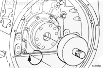
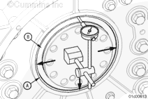
Install the pins into the crankshaft oil seal driver, Part Number 4919705.
NOTE: Make sure the wear sleeve and seal are even before starting installation, or damage to the wear sleeve can occur.
Begin seal installation by carefully tapping the outer edges of the installation tool to make sure the wear sleeve starts correctly.
Use a dead blow hammer or two capscrews, Part Number S-162-B, to install the seal until the installer is positioned against the end of the crankshaft. Make sure to keep the seal perpendicular to the crankshaft during installation.
Hello, I'm Jack, a diesel engine fan and a blogger. I write about how to fix and improve diesel engines, from cars to trucks to generators. I also review the newest models and innovations in the diesel market. If you are interested in learning more about diesel engines, check out my blog and leave your feedback.
View all posts by Jack


;)
;)
;)
;)
;)
;)
;)
;)
;)
;)
;)
;)
;)
;)
;)
;)
;)
;)