Cummins N14 STC, Celect, Celect Plus – Service Manual 016-006   Flywheel Housing

Install

TOC

 CAUTION 

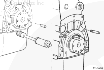
If a new flywheel housing is being installed, the dowels must be removed from the cylinder block prior to installing the housing to prevent damage to the housing. The housing must be doweled with an oversize dowel after it has been aligned.

Install two 5/8 – 18 x 4-inch guide studs, Part Number 3824462, into the cylinder block to help support and align the housing during installation.

SMALL | MEDIUM | LARGE


If a wet-type flywheel housing is being installed, perform the following:

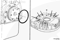
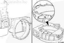
  • Install a new o-ring onto the rear cover. Use 15W-40 oil to lubricate the o-ring.
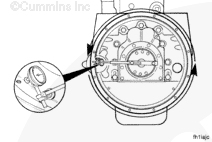
  • Install eleven rectangular sealing rings into the capscrew and dowel pin counterbores in the flywheel housing. Use gasket adhesive to fasten the sealing rings to the housing.

SMALL | MEDIUM | LARGE


Install the flywheel housing over the guide studs.

Install the capscrews, and tighten in the sequence shown.

Torque Value:  203  n.m  [150 ft-lb]

SMALL | MEDIUM | LARGE
   

Measure

TOC

Bore Alignment


 CAUTION 

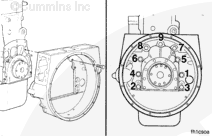
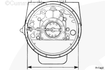
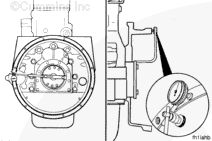
The flywheel housing bore and the surface must be in alignment with the crankshaft to prevent possible damage to the engine, the clutch, or the transmission.

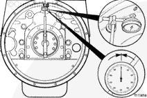
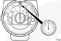
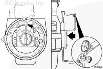
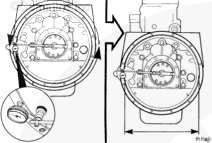
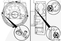
Use chalk to mark the housing at the 12:00 o’clock, 3:00 o’clock, 6:00 o’clock, and 9 o’clock positions.

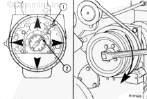
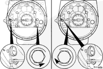
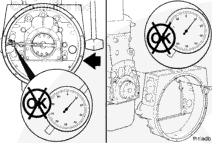
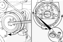
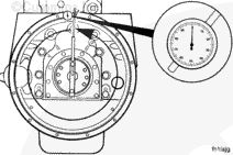
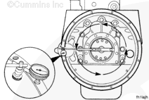
Use the dial gauge indicator (1), Part Number 3376050, and dial gauge attachment (2), Part Number ST-1325, to measure the bore alignment.

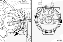
Use the accessory drive shaft to rotate the crankshaft.

SMALL | MEDIUM | LARGE


Attach a dial indicator to the crankshaft, as illustrated.

The indicator arm must be rigid for an accurate reading. It must not sag.

Place the indicator at the 12:00 o’clock position. Adjust the dial indicator until the needle points to “0” (zero).

SMALL | MEDIUM | LARGE


Use the accessory drive to rotate the crankshaft in a clockwise direction (as viewed from the front of the engine).

Record the indicator reading at three different points: 3:00 o’clock, 6:00 o’clock, and 9:00 o’clock.

 
SMALL | MEDIUM | LARGE


Continue rotating the crankshaft until the dial indicator is at the 12:00 o’clock position.

Check the dial indicator to make sure the needle still points to “0” (zero).

SMALL | MEDIUM | LARGE


Determine the total indicator run out as follows:

Total Indicator Run Out (Example)
12:00 O’clock
3:00 O’clock
6:00 O’clock
9:00 O’clock
Total Indicator Run Out
0.00 mm [0.00 in]
+0.08 mm [+0.003 in]
-0.05 mm [-0.002 in]
+ 0.08 mm [+.003 in]
0.13 mm [0.005 in]
 
SMALL | MEDIUM | LARGE


The maximum allowable TIR depends on the diameter of the housing bore. Reference the following chart:

Flywheel Housing Bore Alignment Total Indicator Run Out
SAE Number
Bore Diameter
Bore Location Tolerance
00
787.40 to 787.65 mm [31.000 to 31.010 in]
0.30 mm [0.012 in]
0
647.70 to 647.95 mm [25.500 to 25.510 in]
0.25 mm [0.010 in]
½
584.00 to 584.20 mm [23.000 to 23.008 in]
0.25 mm [0.010 in]
1
534.27 to 534.40 mm [20.125 to 20.130 in]
0.20 mm [0.008 in]
2
447.68 to 447.80 mm [17.625 to 17.630 in]
0.20 mm [0.008 in]
3
409.58 to 409.70 mm [16.125 to 16.130 in]
0.20 mm [0.008 in]
 
SMALL | MEDIUM | LARGE


If the bore alignment does not meet the specifications, loosen the housing capscrews.

Tighten the capscrews again, and measure the bore alignment again.

Flywheel housing misalignment can be confirmed if the dial indicator minimum and maximum readings are exactly 180 degrees apart.

Alignment can be corrected by repositioning the housing.

A flywheel housing bore “Out-of-Round” condition will produce dial indicator minimum and maximum readings in random locations.

 
SMALL | MEDIUM | LARGE


If the alignment is not within specifications and the bore is round, the housing can be shifted.

If the alignment is not within specifications and the bore is not round, the housing must be replaced.

SMALL | MEDIUM | LARGE
   

Face Alignment


 CAUTION 

The tip of the gauge must not enter the capscrew holes or the gauge will be damaged.

Place the tip of the dial indicator gauge against the flywheel housing surface.

SMALL | MEDIUM | LARGE


Use the accessory drive to rotate the crankshaft until the dial indicator is at the 12:00 o’clock position.

Push the crankshaft toward the front of the engine.

Adjust the dial on the indicator until the needle points to “0” (zero).

The crankshaft must be pushed toward the front of the engine to remove the crankshaft end clearance each time a point is measured.

 
SMALL | MEDIUM | LARGE


Use the accessory drive to rotate the crankshaft in the clockwise direction.

Record the indicator reading at three different points: 3:00 o’clock, 6:00 o’clock, and 9:00 o’clock.

 
SMALL | MEDIUM | LARGE


Continue rotating the crankshaft until the dial indicator is at the 12:00 o’clock position.

Check the dial indicator to make sure the needle still points to “0” (zero).

SMALL | MEDIUM | LARGE


Determine the total indicator run out as follows:

Total Indicator Run Out (Example)
12:00 O’clock
3:00 O’clock
6:00 O’clock
9:00 O’clock
Total Indicator Run Out
0.00 mm [0.00 in]
+0.08 mm [+0.003 in]
-0.05 mm [-0.002 in]
+ 0.08 mm [+.003 in]
0.13 mm [0.005 in]
 
SMALL | MEDIUM | LARGE


The maximum allowable TIR depends on the diameter of the housing bore. Reference the following chart:

Flywheel Housing Bore Alignment Total Indicator Run Out
SAE Number
Bore Diameter
Bore Location Tolerance
00
787.40 to 787.65 mm [31.000 to 31.010 in]
0.30 mm [0.012 in]
0
647.70 to 647.95 mm [25.500 to 25.510 in]
0.25 mm [0.010 in]
½
584.00 to 584.20 mm [23.000 to 23.008 in]
0.25 mm [0.010 in]
1
534.27 to 534.40 mm [20.125 to 20.130 in]
0.20 mm [0.008 in]
2
447.68 to 447.80 mm [17.625 to 17.630 in]
0.20 mm [0.008 in]
3
409.58 to 409.70 mm [16.125 to 16.130 in]
0.20 mm [0.008 in]
 
SMALL | MEDIUM | LARGE


If the alignment is not within specifications, remove the housing. Check for nicks, burrs, or foreign material between the block and the housing.

SMALL | MEDIUM | LARGE


Check the alignment again. If the alignment is not within specifications, the block or the housing is not machined correctly.

SMALL | MEDIUM | LARGE
Last Modified:  15-Mar-2012