Flow Diagram
|
TOC |
|
|
|
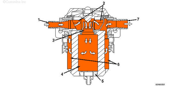
| Crankcase Ventilation System – Normal Operations |
- Filter assembly inlet
- Upper regulator chamber/inertial separator
- Inertial separator oil drain slot
- Inside element
- Oil reservoir
- Filtered blowby
- Filter assembly outlet.
|
Last Modified: 20-Jun-2005
Published by Jack
Hello, I'm Jack, a diesel engine fan and a blogger. I write about how to fix and improve diesel engines, from cars to trucks to generators. I also review the newest models and innovations in the diesel market. If you are interested in learning more about diesel engines, check out my blog and leave your feedback.
View all posts by Jack
;)
;)