To reduce the possibility of personal injury, do not touch any ignition wires or components while the engine is operating, unless using suitably insulated tools.
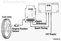
The EPS senses the engine position and timing from the cam gear and provides that signal to the ECM. The ECM provides a spark reference signal and spark-timing signal to the ICM. A 12-VDC supply voltage to the ICM is supplied through the keyswitch. These signals provide ignition at the correct time. By utilizing the ECM to control the timing of the engine, the need for a timing check or timing adjustment is eliminated.
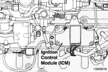
The electronic ICM operates similarly to an automotive electronic ignition system. Through the interconnecting cable assemblies, the ICM sends signals to the ignition coils to fire the spark plugs.
The engine should have OEM-equipped temperature and oil pressure sensors connected to indicators or wired for automatic shutdown. The engine can also be fitted with an OEM block heater or an oil pan heater.
Hello, I'm Jack, a diesel engine fan and a blogger. I write about how to fix and improve diesel engines, from cars to trucks to generators. I also review the newest models and innovations in the diesel market. If you are interested in learning more about diesel engines, check out my blog and leave your feedback.
View all posts by Jack
 WARNING
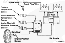
;)
;)
;)
;)
;)
;)