To reduce the possibility of severe personal injury or death when working on the fuel system, turn off the fuel supply at the vehicle’s main fuel shutoff valve before removing any component.
WARNING
Liquefied petroleum gas is normally treated with an odor-producing chemical, so that users will be able to smell fuel leaks. Always be alert for the smell of fuel. If you enter a room or approach a vehicle and a smell of fuel is present, immediately shut off all engines and ignition sources and avoid sparks, arcing switches and equipment, cigarettes, pilot lights, flames, and other sources of ignition in the area and in areas with common ventilation. Provide extra ventilation to the area and do not start the equipment or nearby equipment until the leak is corrected and the area is ventilated. Avoid leaving liquefied petroleum gas-fueled equipment in unvented rooms overnight or for extended periods. Store and service liquefied petroleum gas-fueled equipment in large, well-ventilated areas or outside.
WARNING
Liquefied petroleum gas is heavier than air and can accumulate near the floor, in sumps, and in low-lying areas.
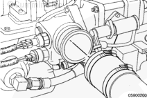
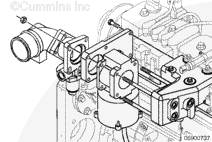
Turn off the vehicle’s main fuel valve.
Operate the engine at low idle until the engine dies or bleed the fuel from the fuel filter.
The pressure of the fuel in the line is sufficient to penetrate the skin and cause serious personal injury. Wear gloves and protective clothing.
WARNING
Fuel is flammable. Keep all cigarettes, flames, pilot lights, arcing equipment, and switches out of the work area and areas sharing ventilation to reduce the possibility of severe personal injury or death when working on the fuel system.
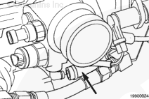
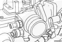
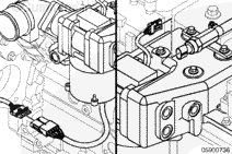
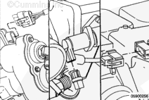
On B5.9G and B5.9LPG engines, be sure to use two wrenches when tightening the hose. Twisting and damage will occur to the fuel jumper hose if only one wrench is used.
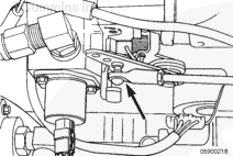
Install the fuel jumper hose.
Torque Value: 77 n.m [57 ft-lb]
NOTE: The fuel jumper hose used on B5.9G and B5.9LPG engines is different than the one used on B Gas Plus and B LPG Plus engines.
Fuel is flammable. Keep all cigarettes, flames, pilot lights, arcing equipment, and switches out of the work area and areas sharing ventilation to reduce the possibility of severe personal injury or death when working on the fuel system.
On B5.9G and B5.9LPG engines, be sure to use two wrenches when tightening the hose. Twisting and damage will occur to the fuel jumper hose if only one wrench is used.
Fuel is flammable. Keep all cigarettes, flames, pilot lights, arcing equipment, and switches out of the work area and areas sharing ventilation to reduce the possibility of severe personal injury or death when working on the fuel system.
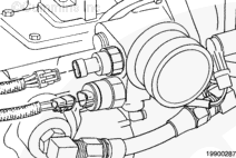
Turn on the vehicle’s main fuel supply valve.
NOTE: The fuel jumper hose used on B5.9G and B5.9LPG engines is different than the one used on B Gas Plus and B LPG Plus engines.
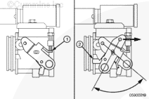
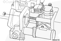
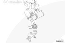
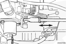
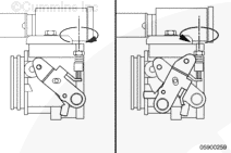
When connecting the linkage to the throttle control lever, adjust the length so the lever has minimum stop-to-stop movement from idle (1) to wide-open throttle (2).
The break-over spring, second spring on the lever (1), is to make sure that the throttle linkage does not break from overextension. The break-over spring will actually close down the throttle plate if it is overengaged.
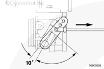
Do not exceed break-over spring travel by more than 10 degrees past wide-open throttle stop.
With the throttle pedal fully depressed, verify on INSITE™ that the throttle percent reading on the INSITE™ monitor screen is greater than 85 percent. If the INSITE™ reading is not 85 percent, adjust the linkage.
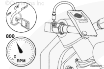
Use INSITE™, not the vehicle tachometer, to check engine speed. INSITE™ is more accurate.
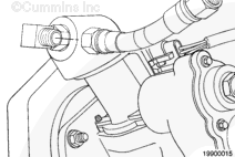
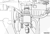
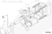
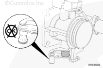
Adjust the idle screw as follows:
Turn screw clockwise to increase speed.
Turn screw counterclockwise to decrease speed.
Adjust the setscrew until the engine idles between 600 to 650 rpm.
Verify that at no-throttle pedal INSITE™ reads 0-percent throttle.
(If INSITE™ does not read 0-percent throttle at idle, the ECM will think the throttle pedal is being depressed and will not
use the idle bypass to control idle speed.)
The engine can die when the idle speed control valve is unplugged. Make sure the accessory load is at a minimum.
The setscrew is extremely sensitive. Use quarter turns.
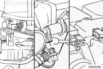
When the base idle adjustment has been completed, reconnect the idle control valve.
Hello, I'm Jack, a diesel engine fan and a blogger. I write about how to fix and improve diesel engines, from cars to trucks to generators. I also review the newest models and innovations in the diesel market. If you are interested in learning more about diesel engines, check out my blog and leave your feedback.
View all posts by Jack

 WARNING
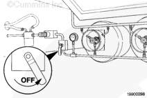


 CAUTION
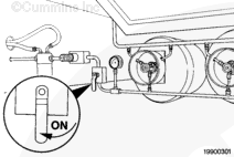
;)
;)
;)
;)
;)
;)
;)
;)
;)
;)
;)
;)
;)
;)
;)
;)
;)
;)
;)
;)
;)
;)
;)
;)
;)
;)
;)
;)
;)
;)
;)
;)
;)
;)
;)
;)
;)
;)
;)
;)
;)
;)
;)
;)