Steam clean the air compressor and dry with compressed air.
Drain the engine coolant if the air compressor has a liquid cooled cylinder head. If compressor is air cooled, then the engine coolant need not be drained.
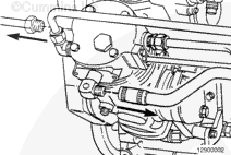
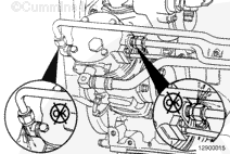
Open the draincock on the wet tank to release air from the system. Close the draincock after the pressure is released.
Air Compressor Timing (for single cylinder air compressor only)
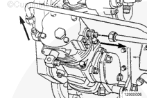
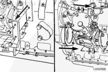
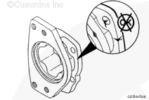
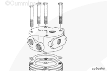
Locate TDC on the compressor crankshaft by removing the unloader valve or head, (refer to the (respective) air compressor manual). TDC does not have to be exact. The system is tolerant of some misalignment.
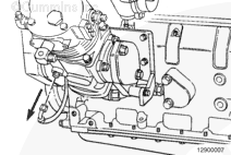
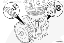
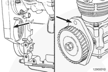
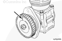
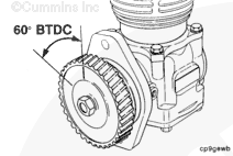
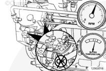
Rotate the compressor TDC mark to 60 degrees, or 6 teeth on a 36 tooth gear, before TDC. This is approximately 10:00 o’clock when viewed from the front of the air compressor.
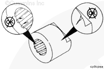
NOTE: Holset® air compressors Series SS, QE220, 296 and 338 will have a radial line etched on the gear representing TDC.
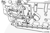
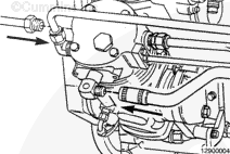
If rubber grommets are used on the coolant or air lines, be sure they are installed carefully to prevent cuts or tears to the grommets which will cause leaks.
Hello, I'm Jack, a diesel engine fan and a blogger. I write about how to fix and improve diesel engines, from cars to trucks to generators. I also review the newest models and innovations in the diesel market. If you are interested in learning more about diesel engines, check out my blog and leave your feedback.
View all posts by Jack


 CAUTION
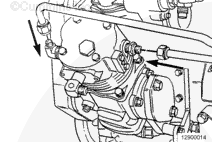
;)
;)
;)
;)
;)
;)
;)
;)
;)
;)
;)
;)
;)
;)
;)
;)
;)
;)
;)
;)
;)
;)
;)
;)
;)
;)
;)
;)
;)
;)
;)
;)
;)
;)
;)
;)
;)
;)
;)
;)
;)
;)