If upper bore erosion is discovered during block inspection, it must be disregarded. It is not a failure mode and the use of new o-rings on the cylinder liner provides an adequate seal.
If liner ledge pitting is discovered during block inspection, the block can be reused, if no leak is evident in the liner-to-liner ledge (block) interface.
The main bearing bore diameter must be measured with the main bearings removed and the main bearing caps assembled and torqued to the correct specification.
Follow this procedure to salvage capscrew holes that are missing a portion of threads or that have cracks extending into the threaded sidewall from the upper counterbore.
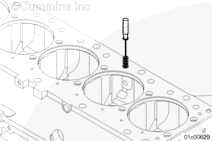
Remove any burrs from the top deck surface of the cylinder block. A 12 inch flat surface mill file is effective for this step. Burr removal is necessary to obtain an accurate fixture location.
NOTE: The thread salvage kit is designed to be used with the cylinder liner removed. If the cylinder liner remains in the block, shims must be installed to both sides of the base, equally, to bridge the liner.
NOTE: On some engines, it will be necessary to use the spacer, Part Number 3376206, between the mounting base and the drilling fixture.
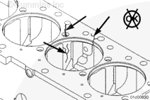
Select two capscrew holes so the failed capscrew hole is positioned approximately in the middle. Install the mounting plate assembly onto the capscrew holes using the appropriate spacers, four plain washers, and the existing cylinder head capscrews.
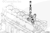
Use a heavy washer and the 5/8-18 x 3 inch hex head capscrew to attach the drilling fixture to the mounting plate assembly.
For main bearing capscrew thread repair, mounting plate, Part Number 3164014, will not accommodate all engines. In those cases, the repair must be performed by a qualified machine shop.
Setting the stop collar is required only for repairs using drills.
Drills are used in some kits to allow for quick removal of waste material; however, care must be taken to make certain the depth of the repaired capscrew hole is not increased beyond specification.
The following steps will result in the drill stopping short of the original hole depth. The remaining material is then removed with the reamer.
Place a 0.76 mm [0.030 in] feeler gauge over the hole to be repaired.
Insert the drill through the drill bushing until its tip rests against the feeler gauge.
Place the thread insert to be installed between the drill bushing and the stop collar.
Move the stop collar down until is rests against the insert and tighten the stop collar.
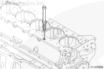
Place the drill through the drill fixture bushing and let it rest over the top of the failed capscrew hole.
Use a drill motor with a clutch and a maximum operating speed of 300 rpm. Use a suitable cutting fluid. Operate the drill motor until the stop collar contacts the drill bushing.
Place the reamer through the drill fixture bushing and let it rest over the top of the failed capscrew hole.
While reaming the hole, it will be necessary to stop frequently to clean the hole with the chip vacuum.
Use a drill motor with a clutch and a maximum operating speed of 300 rpm, a suitable cutting fluid and operate the drill motor until the reamer reaches the bottom of the original capscrew hole.
The reamer will stop cutting when it reaches the bottom of the hole.
When using solvents, acids, or alkaline materials for cleaning, follow the manufacturer’s recommendations for use. Wear goggles and protective clothing to reduce the possibility of personal injury.
WARNING
Some solvents are flammable and toxic. Read the manufacturer’s instructions before using.
Check the capscrew hole for evidence of porosity and cracks.
Clean the threads and flush any debris from the tapped hole using a solvent-degreasing agent.
When using solvents, acids, or alkaline materials for cleaning, follow the manufacturer’s recommendations for use. Wear goggles and protective clothing to reduce the possibility of personal injury.
WARNING
Some solvents are flammable and toxic. Read the manufacturer’s instructions before using.
Remove the preservative coating from the circumference of the thread insert. Use a solvent-degreasing agent.
Prior to increasing the capscrew hole depth, check the following:
Make certain the correct thread insert is being used. Two inserts are available, two inserts are identical except for their length.
Make certain the insert used is the correct length.
Make certain the capscrew hole is threaded all the way to the bottom.
Make certain there are no burrs or other damage that would prevent the insert from threading to the bottom of the capscrew hole.
After checking the above listed items, if the thread insert protrusion still exceeds 1.0 mm [0.040 in], the depth of the original capscrew hole must be increased.
NOTE: The thread salvage kit is designed to be used with the cylinder liner removed. If the cylinder liner remains in the block, shims must be installed to both sides of the base, equally, to bridge the liner.
NOTE: On some engines, it will be necessary to use the spacer, Part Number 3376206, between the mounting base and drilling fixture.
Install the mounting plate assembly.
Do not tighten the fasteners.
Slide the drill through the drill bushing and into the threaded hole until it rests at the bottom of the hole.
Tighten all fasteners.
Torque Value: 68 n.m [50 ft-lb]
The drill must slide freely in the bushing and threaded hole, indicating that it is centered in the hole.
Do not increase the depth of the original capscrew hole more than 3.0 mm [0.120 in].
Slide the stop collar over the drill bit.
Subtract 0.50 mm [0.020 in] from the insert protrusion.
Select a feeler gauge equivalent to this value.
With the drill resting at the bottom of the hole, insert the feeler gauge between the stop collar and drill bushing.
Tighten the stop collar.
Use a drill motor with a clutch and a maximum operating speed of 300 rpm, a suitable cutting fluid and operate the drill motor until the stop collar contacts the drill bushing.
When using solvents, acids, or alkaline materials for cleaning, follow the manufacturer’s recommendations for use. Wear goggles and protective clothing to reduce the possibility of personal injury.
WARNING
Some solvents are flammable and toxic. Read the manufacturer’s instructions before using.
Check the capscrew hole for evidence of porosity and cracks.
Clean the threads, and flush any debris from the tapped hole using a solvent-degreasing agent.
Install the thread insert on a cylinder head capscrew and lock in place with a jam nut.
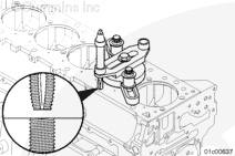
Temporarily install the thread insert and check the protrusion. Make certain that the protrusion is 0 to 1 mm [0 to 0.040 in] above the cylinder block surface.
For applications where the thread insert is recessed into a counterbore, an end mill or a machine cutter will be necessary to remove the excess length of the insert and restore the alignment of counterbore.
Hello, I'm Jack, a diesel engine fan and a blogger. I write about how to fix and improve diesel engines, from cars to trucks to generators. I also review the newest models and innovations in the diesel market. If you are interested in learning more about diesel engines, check out my blog and leave your feedback.
View all posts by Jack


 WARNING


;)
;)
;)
;)
;)
;)
;)
;)
;)
;)
;)
;)
;)
;)
;)
;)
;)
;)
;)
;)
;)
;)
;)
;)
;)
;)
;)
;)
;)
;)
;)
;)
;)
;)
;)
;)
;)
;)
;)
;)
;)
;)
;)
;)
;)
;)
;)
;)
;)
;)