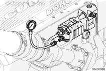
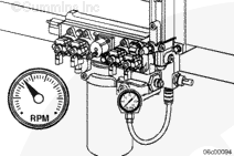
Install a pressure gauge, Part Number 3824877 (2758 kPa [400 psi]), on the fuel pump Compuchek™ fitting, to measure the fuel pressure before the fuel filter.
Install a pressure gauge, Part Number 3824877 (275 kPa [400 psi]), on the rail fuel pressure Compuchek™ fitting located on the IFSM to measure the fuel pressure after the filter.
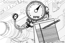
Connect a vacuum gauge to either suction-side Compuchek™ fitting.
NOTE: Some engines equipped with priming pumps do not have a lower Compuchek™ fitting and have an air bleed line plumbed into the upper location. Reference the Install Section for measuring inlet restriction.
An inlet restriction greater than specification indicates either a dirty fuel filter or a restriction in the OEM fuel supply plumbing. Inlet restriction at the fuel supply connection must be checked to identify the correct source of the restriction.
Fuel is flammable. Keep all cigarettes, flames, pilot lights, arcing equipment, and switches out of the work area and areas sharing ventilation to reduce the possibility of severe personal injury or death when working on the fuel system.
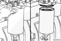
Clean the area around the fuel filter head and filter.
Remove the fuel filter with filter wrench, Part Number 3400157.
Fuel is flammable. Keep all cigarettes, flames, pilot lights, arcing equipment, and switches out of the work area and areas sharing ventilation to reduce the possibility of severe personal injury or death when working on the fuel system.
Clean the area around the fuel filter head and filter.
Disconnect the wiring harness from the water-in-fuel sensor, if equipped.
Remove the fuel filter with filter wrench, Part Number 3400158.
Use the correct filter(s) for your engine. It must remove a minimum of 95 percent of free and emulsified water. It must also have a minimum of 98.7 percent 15-micron particle-removal efficiency.
To perform the priming procedure, use the following items to fabricate a fuel bypass hose:
2- Quick-disconnect fittings, Part Number 3376859
Clear tubing (capable of 2758 kPa [400 psi])
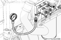
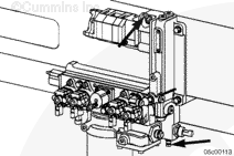
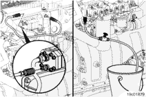
Install the fuel bypass hose fabricated above between the suction-side Compuchek™ fitting at the top of the IFSM and the fuel pump Compuchek™ fitting located on the head of the fuel pump.
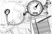
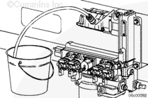
Connect the clear hose and the shutoff valve normally used to check for air-in-fuel to the rail Compuchek™ fitting. Refer to Procedure 006-003 in Section 6. Place the open end of the tube in a suitable container and fully open the shutoff valve in the hose.
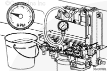
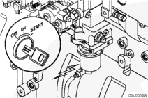
Fill the fuel filter by turning the ignition switch to the ON position, but do not start the engine. The fuel lift pump should begin to operate. Monitor the open end of the bleed line from the rail Compuchek™. When fuel is seen coming out of this line, turn the ignition OFF. Remove the bleed line and the air-in-fuel test line.
Use the correct filter(s) for your engine. It must remove a minimum of 95 percent of free and emulsified water. It must also have a minimum of 98.7 percent at 25-micron particle-removal efficiency.
NOTE: The engine will, perhaps, run rough for several minutes until the air is out of the system.
Fill the fuel filter by turning the ignition keyswitch to the ON position. The priming pump will operate for 2 minutes, which will adequately fill the fuel filter. The engine can then be started.
Some engines utilize a manual, remote mount priming pump. Flip the priming pump mounted toggle switch to the ON position. Operate the pump for 2 minutes and shut it off. The engine can then be started.
With Vacuum Fuel Filtering and Without Priming Pump
Use the correct filter(s) for your engine. It must remove a minimum of 95 percent of free and emulsified water. It must also have a minimum of 98.7 percent at 25-micron particle-removal efficiency.
Mechanical overtightening of the filter can distort the threads or damage the filter element seal.
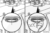
NOTE: If the filter is equipped with a water-in-fuel sensor, rotate the sensor on the filter to the desired location and connect the wiring harness. Fill the filter with clean fuel prior to installation.
Install the filter onto the filter head. Turn the filter until the gasket contacts the filter head surface.
Tighten the filter an additional 3/4 of a turn after the gasket contacts the filter head surface, or as specified by the filter manufacturer.
NOTE: The engine will, perhaps, run rough for several minutes until the air is out of the system.
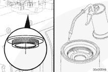
Remove the external hex plug on the top ofthe integrated fuel system module. Crank the engine until a solid stream of fuel comes out of the port.
Install the hex plug.
Crank the engine for 20 seconds. If the engine does not start within 20 seconds, wait two minutes. It will probably be necessary to remove the filter, fill the filter with clean fuel, and install the filter.
Hello, I'm Jack, a diesel engine fan and a blogger. I write about how to fix and improve diesel engines, from cars to trucks to generators. I also review the newest models and innovations in the diesel market. If you are interested in learning more about diesel engines, check out my blog and leave your feedback.
View all posts by Jack


 WARNING


 CAUTION
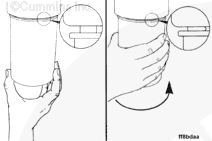
;)
;)
;)
;)
;)
;)
;)
;)
;)
;)
;)
;)
;)
;)
;)
;)
;)
;)
;)
;)
;)
;)
;)
;)
;)
;)
;)
;)
;)
;)