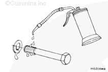
To reduce the possibility of personal injury, avoid direct contact of hot oil with your skin
WARNING
Some state and federal agencies have determined that used engine oil can be carcinogenic and cause reproductive toxicity. Avoid inhalation of vapors, ingestion, and prolonged contact with used engine oil. If not reused, dispose of in accordance with local environmental regulations.
Cummins Inc., recommends replacing the thrust bearings when the main bearings are replaced.
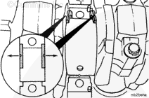
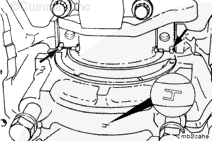
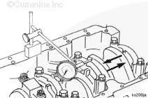
Push the crankshaft toward the rear of the engine to install the rear thrust bearing, and to the front of the engine to install the front thrust bearing.
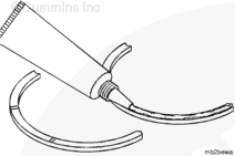
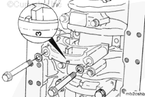
Install the upper thrust bearings in the number four main bearing saddle.
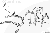
To avoid the possibility of damage to the cylinder block and main bearing cap, the number four main bearing cap must be aligned with the dowel pins in the bearing saddle when the capscrews are tightened.
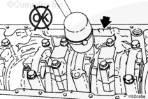
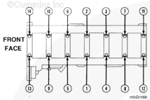
The main bearing caps are numbered one through seven from front to rear in the cylinder block. The caps must be installed so the number on the cap matches the bearing saddle in the block. The lock tangs in the main bearing saddle and bearing cap must be on the same side.
Make certain that the proper main cap capscrew torque procedure is used when torquing main bearings. The use of the improper torque procedure will damage the engine. Refer to Procedure 001-006 in Section 1.
Operate the engine to normal operating temperature and check for leaks.
NOTE: The engine must have adequate oil pressure within 15 seconds after starting. If the warning light indicating low oil pressure has not gone out or there is no oil pressure indicated on a gauge within 15 seconds, shut off the engine immediately to avoid engine damage. Confirm the correct oil level is in the oil pan.
Hello, I'm Jack, a diesel engine fan and a blogger. I write about how to fix and improve diesel engines, from cars to trucks to generators. I also review the newest models and innovations in the diesel market. If you are interested in learning more about diesel engines, check out my blog and leave your feedback.
View all posts by Jack
 WARNING


 CAUTION


;)
;)
;)
;)
;)
;)
;)
;)
;)
;)
;)
;)
;)
;)
;)
;)
;)
;)
;)
;)
;)
;)
;)
;)