To reduce the possibility of damage to the connector pins, do not use probes or leads other than Part Numbers 3164110 and 3164112. The leads must fit tightly in the connector without expanding the pins of the connector.
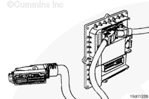
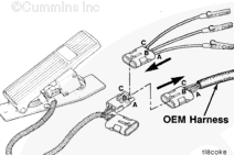
Disconnect the OEM harness 89-pin connector from the ECM.
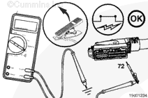
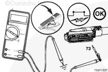
Touch one multimeter probe to vehicle ground. Insert the other test lead into pin 72 (on-idle signal) of the OEM harness connector. Attach the lead to the multimeter probe.
Make sure the idle validation switch is connected to the circuit. Make sure the accelerator pedal is in the idle (released) position. Measure the resistance.
The multimeter
must show 10 ohms or less for separate sensor/switch pedals and 125 ohms or less for integrated sensor/switch pedals.
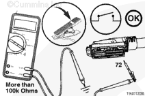
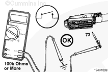
Slowly depress the accelerator pedal, and measure the resistance.
The multimeter
must show an open circuit (100k ohms or more) when depressed to the OFF-IDLE position.
If the resistance values are
not within the specifications for the previous two checks, there is a problem in the OEM harness, provided the idle validation switch has been previously checked. Repair or replace the OEM harness. Refer to Procedure
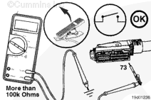
Slowly depress the accelerator pedal, and measure the resistance.
The multimeter
must show 10 ohms or less for separate sensor/switch pedals and 125 ohms or less for integrated sensor/switch pedals when in the OFF-IDLE zone of the pedal travel.
If the resistance values are
not within the specifications for the two previous checks, there is a problem in the OEM harness, provided the idle validation switch has been previously checked. Repair or replace the OEM harness. Refer to Procedure
NOTE: When checking the OEM harness, examine the bulkhead connector and other connectors in the circuit for corrosion or damage to the idle validation switch terminals.
To reduce the possibility of damage to the connector pins, do not use probes or leads other than Part Number 3164112. The leads must fit tightly in the connector without expanding the pins of the connector.
To isolate the idle validation switch circuit when checking for a short circuit, turn all cab panel switches to the OFF or NEUTRAL position.
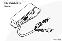
Disconnect the idle validation switch from the accelerator pedal assembly.
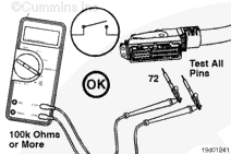
Insert one test lead into pin 72 (on-idle signal), and attach the lead to the multimeter probe. Touch the other multimeter probe to ground, and measure the resistance.
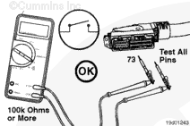
Remove the test lead from pin 72 and insert it into pin 73 (off-idle signal). Touch the other multimeter probe to ground, and measure the resistance.
The multimeter
must show an open circuit (100k ohms or more).
If the multimeter does
not show an open circuit (100k ohms or more), there is a short circuit to ground between the wires connected on the on-idle and off-idle signals. Repair or replace the OEM harness. Refer to Procedure
To reduce the possibility of damage to the connector pins, do not use probes or leads other than Part Numbers 3164110 and 3164112. The leads must fit tightly in the connector without expanding the pins of the connector.
Disconnect the idle validation switch from the OEM harness at the accelerator pedal assembly.
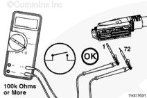
Insert the appropriate test lead into pin 72 (on-idle signal) of the OEM harness connector, and insert the other appropriate test lead into pin 1 of the connector. Attach the leads to the multimeter probes, and measure the resistance.
Remove the lead from pin 1, and check all other pins in the connector.
The multimeter
must show an open circuit (100k ohms or more) at all pins.
If the multimeter shows a closed circuit at any pin, there is a short circuit between pin 72 (on-idle signal) and any wire that measured a closed circuit.
Repair or replace the OEM harness. Refer to Procedure
Remove the lead from pin 72 (on-idle signal) and insert it into pin 73 (off-idle signal). Insert the other test lead into pin 1, and measure the resistance.
Remove the lead from pin 1, and check all other pins.
If the multimeter shows a closed circuit at any pin, there is a short circuit between pin 73 (off-idle signal) and any other pin that measured a closed circuit. Repair or replace the OEM harness. Refer to Procedure
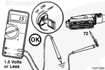
Set the multimeter to measure VDC. Insert one test lead into pin 72
(on-idle signal) of the OEM harness connector. Attach the lead to the multimeter positive (+) probe. Touch the multimeter negative (-) probe to ground, and measure the voltage.
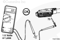
Remove the lead from pin 72 (on-idle signal) and insert it into pin 73 (off-idle signal). Touch the multimeter negative (-) probe to ground, and measure the voltage.
The voltage
must be 1.5 VDC or less.
If the voltage is more than 1.5 VDC at any pin, there is a short circuit from the on-idle signal wire or the off-idle signal wire to a wire carrying power in the OEM harness.
Repair or replace the OEM harness. Refer to Procedure
Hello, I'm Jack, a diesel engine fan and a blogger. I write about how to fix and improve diesel engines, from cars to trucks to generators. I also review the newest models and innovations in the diesel market. If you are interested in learning more about diesel engines, check out my blog and leave your feedback.
View all posts by Jack

 CAUTION


;)
;)
;)
;)
;)
;)
;)
;)
;)
;)
;)
;)
;)
;)
;)
;)
;)
;)
;)
;)
;)
;)
;)
;)
;)
;)
;)
;)
;)
;)