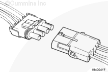
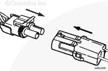
The connector is used to connect many different sensors and switches to the engine, OEM interface, and OEM harnesses. The connector can be a two-way or a four-way pin type. All types of connectors are repaired in the same manner. The four-way connector is displayed in this procedure.
NOTE: Make sure the correct wires are connected to the correct connectors. Refer to the wiring diagram in
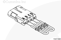
If more than one wire is being repaired, tag each wire, and install in the original location to reduce the possibility of incorrectly wiring the connector.
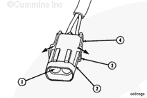
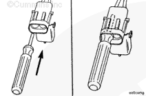
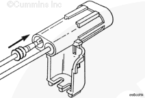
Pull the wire and the terminal out of the connector body.
NOTE: The repair wire and terminal is 127 mm [5 in] long.
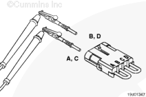
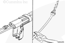
Use wire cutters to cut 127 mm [5 in] off the terminal and wire.
If more than one wire is repaired or if the connector body is replaced, be sure to insert the wires into the same locations as they were in the original connector to reduce the possibility of incorrectly wiring the connector to reduce the possibility of incorrectly wiring the connector.
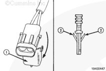
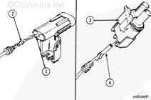
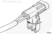
Insert the terminal into the connector body. The terminal locking lances
Hello, I'm Jack, a diesel engine fan and a blogger. I write about how to fix and improve diesel engines, from cars to trucks to generators. I also review the newest models and innovations in the diesel market. If you are interested in learning more about diesel engines, check out my blog and leave your feedback.
View all posts by Jack





 CAUTION
;)
;)
;)
;)
;)
;)
;)
;)
;)
;)
;)
;)
;)
;)
;)
;)
;)
;)
;)
;)
;)
;)
