When using a steam cleaner, wear protective clothing, as well as safety glasses or a face shield. Hot steam can cause serious personal injury.
WARNING
Compressed air used for cleaning should not exceed 207 kPa [30 psi]. Wear protective clothing, safety goggle/shield, and gloves.
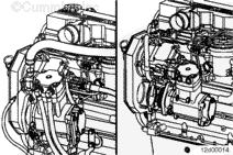
NOTE: The illustrations shown will be of the QE model single-cylinder air compressor. Differences in procedures for QE and HD model Cummins air compressors will be shown where necessary.
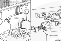
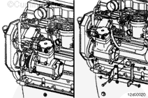
Use steam to clean the air compressor.
Dry with compressed air.
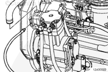
Remove the hydraulic pump, if equipped. Refer to Procedure 009-016.
Coolant is toxic. Keep away from pets and children. If not reused, dispose of in accordance with local environmental regulations.
WARNING
Do not remove the pressure cap from a hot engine. Wait until the temperature is below 50°C [120°F] before removing the pressure cap. Heated coolant spray or steam can cause personal injury.
Drain the engine coolant. Refer to Procedure 008-018.
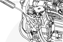
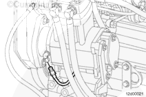
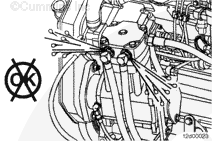
Remove the coolant lines from the air compressor.
NOTE: If the air compressor does not have a liquid-cooled cylinder head, then this step is not necessary.
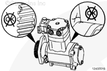
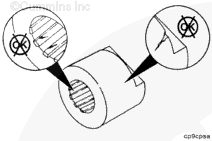
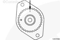
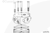
NOTE: There are two similar marks on the air compressor gear that look like “[l]”
and “l”. The timing mark that is to be used when timing the air compressor to the engine is “l”.
Viewing the compressor from the gear end (with the compressor in a vertical position), rotate the gear so the “l” timing mark is at the 12-o’clock position. This will set the compressor at 60 degrees before top dead center of the compressors’ compression stroke.
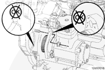
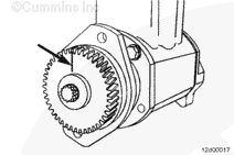
NOTE: Some Holset® compressors have a divot/drilling on the housing at the 10-o’clock position; ignore this mark.
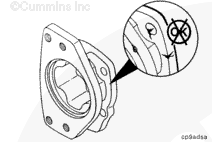
Viewing the compressor from the gear end (with the compressor in a vertical position), rotate the gear so the “l” timing mark is at the 3-o’clock position. The Cummins Single-Cylinder air compressor will have a divot on the housing at the 3-o’clock position to aid in timing the compressor. Once the timing mark is at the 3-o’clock position, this will set the compressor at 60 degrees before top dead center of the compressors’ compression stroke.
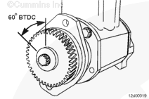
Air Compressor Timing (for Single-Cylinder Air Compressor Only, Other than Holset® or Cummins)
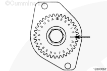
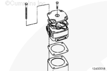
Locate TDC on the compressor crankshaft by removing the unloader valve or head. (Refer to the respective air compressor manual.) TDC does not have to be exact. The system is tolerant of some misalignment.
Rotate the compressor TDC mark to 60 degrees, or six teeth on a 36-tooth gear, before TDC. This is approximately 10-o’clock when viewed from the front of the air compressor.
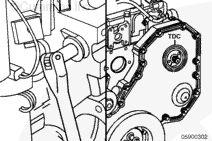
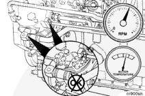
Locate top dead center (TDC) for cylinder Number 1 by barring the crankshaft slowly while aligning the mark on the fuel pump drive gear with the top dead center (TDC) mark.
If rubber grommets are used on the coolant or air lines, be sure they are installed carefully to prevent cuts or tears to the grommets, which will cause leaks.
Hello, I'm Jack, a diesel engine fan and a blogger. I write about how to fix and improve diesel engines, from cars to trucks to generators. I also review the newest models and innovations in the diesel market. If you are interested in learning more about diesel engines, check out my blog and leave your feedback.
View all posts by Jack
 WARNING


 CAUTION
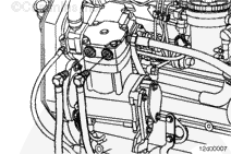
;)
;)
;)
;)
;)
;)
;)
;)
;)
;)
;)
;)
;)
;)
;)
;)
;)
;)
;)
;)
;)
;)
;)
;)
;)
;)
;)
;)
;)
;)
;)
;)
;)
;)
;)
;)
;)
;)
;)
;)