|
Engine Misfire for Multiple Cylinders – Data Valid But Below Normal Operational Level – Most Severe Level
|

Overview
| CODE | REASON | EFFECT |
| Fault Code: 613 PID: None SPN: 1322 FMI: 11/31 LAMP: Red SRT: |
Engine Misfire for Multiple Cylinders – Data Valid But Below Normal Operational Level – Most Severe Level |
Progressive power derate increasing in severity from time of alert. Fault will |
|
Ignition System Circuit |
 |
Circuit Description
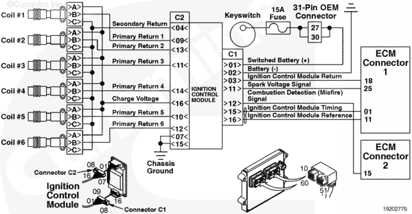
The ignition system is a coil on plug system that uses a separate ignition control module (ICM) to operate the ignition system. Spark timing is controlled by the ECM. The ECM commands the ICM to energize the ignition coil for the proper cylinder in the firing sequence over the ICM timing line in the engine harness. The ECM sends a signal to the ICM to prepare to energize the ignition coil for cylinder number 1 over the ICM reference line in the engine harness. The coils are energized by the ICM through the charge voltage and primary return lines in the ignition harness. The ICM is capable of measuring spark voltage and detecting misfire over the secondary return wire in the ignition harness. The ECM receives this information over spark voltage signal and combustion detection (misfire) signal lines.
Component Location
The ICM is located next to the ECM on the intake side of the engine near the flywheel housing. The ignition coils are located above the corresponding cylinder on the intake side of the engine.
Conditions for Running the Diagnostics
This diagnostic runs continuously when the engine is operating.
Conditions for Setting the Fault Codes
The ECM detects the engine misfire percentage for all cylinders is greater than a calibrated value.
Action Taken When the Fault Code is Active
The ECM logs this fault immediately when the diagnostic runs and fails.
Conditions for Clearing the Fault Code
To validate the repair, start the engine and operate the engine in the condition in which the misfire occurred.
- The ECM will turn the fault inactive immediately after the ECM detects the misfire percentage for all cylinders has dropped below a calibrated value.
- This fault code can also be cleared with INSITE™ electronic service tool.
Shop Talk
If the ECM does not receive a signal on the secondary return wire after a cylinder has been commanded to fire, the ECM will log this as a misfire. In addition to the three misfire faults for each cylinder, misfire percentages are also calculated over all six cylinders. There are three levels of severity for misfire on multiple cylinders.
Possible causes for the Fault Code 613 include:
- Spark plugs past maintenance intervals
- Damaged spark plugs or boots
- Malfunctioning coils
- Shorted or open ignition harness
In addition, misfires on multiple cylinders may be caused by low fuel pressure, EGR, voltage supply, fuel system, or oxygen sensor issues. Any fault codes for these systems should be resolved prior to troubleshooting the misfire compliant.
Misfires may
not occur under all operating conditions. Be sure to operate the engine under the conditions in which the misfire occurs when troubleshooting.
All secondary return wires in the ignition harness are tied together. This way there will be continuity through each secondary return pin of each coil to the main secondary return wire at the ignition harness connector 2. If one of the secondary return wires is found to be open, the ICM will determine that the engine is misfiring when it is not.
Physical damage to the tip of the spark plug and/or traces of aluminum can indicate a damaged piston.
Cautions and Warnings
 WARNING WARNING To reduce the possibility of personal injury, do not touch any ignition wires or components while the engine is operating, unless using suitably insulated tools.
|
|
WARNING The ignition system produces high voltage. To reduce the possibility of personal injury from electrical shock, do not touch any ignition wires or components while the engine is operating. Always use suitably insulated tools.
|
Troubleshooting Steps
| STEPS | SPECIFICATIONS | |
|---|---|---|
| STEP 1. | Check the fault codes. | |
| STEP 1A. Check for an active fault code. | Any non-ignition related fault codes? | |
| STEP 1B. Check for an active fault code. | Fault Code 613 active? | |
| STEP 2. | Check the ignition coils and spark plugs. | |
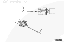
| STEP 2A. Inspect the ignition coil connector pins. | Dirty or damaged pins? | |
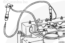
| STEP 2B. Check for voltage at the coils. | Steady spark observed? | |
| STEP 2C. Check the spark plugs. | Spark plug damage or wear? | |
| STEP 3. | Check the ICM and ignition harness. | |
| STEP 3A. Inspect the ICM and ignition harness connector pins. | Dirty or damaged pins? | |
| STEP 3B. Check for an open circuit in the ignition harness. | Less than 10 ohms? | |
| STEP 3C. Check for a pin short circuit to ground in the ignition harness. | Greater than 100k ohms? | |
| STEP 3D. Check for a pin-to-pin short circuit in the ignition harness. | Greater than 100k ohms? | |
| STEP 3E. Check for voltage at the coils. | Steady spark observed? | |
| STEP 3F. Check for voltage at the coils. | Steady spark observed? | |
| STEP 4. | Check ECM calibration and clear fault codes. | |
| STEP 4A. Check if an ECM calibration update is available. | If a calibration update for this fault code is available, does the ECM contain that revision or higher? | |
| STEP 4B. Disable the fault code. | Fault code inactive? | |
Guided Step 1 – Check the fault codes.
| Guided Step 1A – Check for an active fault code. | |
|---|---|
Conditions
ActionOperate the engine under the conditions in which the misfire occured.
|
|
|
Any non-ignition related fault codes? |
|
| YES | NO |
| No Repair | No Repair |
|
Troubleshoot the non-ignition related fault codes.
|
|
| Guided Step 1B – Check for an active fault code. | |
|---|---|
Conditions
ActionOperate the engine under the conditions in which the misfire occured.
|
|
|
Fault Code 613 active? |
|
| YES | NO |
| No Repair | No Repair |
Guided Step 2 – Check the ignition coils and spark plugs.
| Guided Step 2A – Inspect the ignition coil connector pins. | |
|---|---|
Conditions
ActionInspect the ignition harness and ignition coil connector pins of the misfiring cylinders for the following:
Use the following procedure for general inspection techniques. |
|
|
Dirty or damaged pins? |
|
| YES | NO |
|
A damaged connection has been detected in the ignition coil or ignition harness connectors. Repair or replace the harness, or replace the ignition coil, whichever has the damaged pins.
|
No Repair |
| Guided Step 2B – Check for voltage at the coils. | |
|---|---|
Conditions
ActionCheck the ignition coils of the misfiring cylinders.
NOTE: The coils |
|
|
Steady spark observed? |
|
| YES | NO |
| No Repair | No Repair |
| Guided Step 2C – Check the spark plugs. | |
|---|---|
Conditions
ActionInspect the spark plugs for the following.
|
|
|
Spark plug damage or wear? |
|
| YES | NO |
|
No Repair |
Guided Step 3 – Check the ICM and ignition harness.
| Guided Step 3A – Inspect the ICM and ignition harness connector pins. | |
|---|---|
Conditions
ActionInspect the Iignition harness and ICM connector pins of the misfiring cylinders for the following:
Do Use the following procedure for general inspection techniques. |
|
|
Dirty or damaged pins? |
|
| YES | NO |
|
A damaged connection has been detected in the ICM or ignition harness connector. Repair the harness, whichever has the damaged pins.
|
No Repair |
| Guided Step 3B – Check for an open circuit in the ignition harness. | ||
|---|---|---|
Conditions
ActionCheck for an open circuit in the ignition harness.
Refer to the circuit diagram or wiring diagram for connector pin identification. Use the following procedure for general resistance measurement techniques. |
|
|
|
Less than 10 ohms? |
||
| YES | NO | |
| No Repair |
A pin to ground short circuit has been detected in the ignition harness. Repair or replace the ignition harness.
|
|
| Guided Step 3C – Check for a pin short circuit to ground in the ignition harness. | |
|---|---|
Conditions
ActionCheck for an open circuit in the ignition harness.
Refer to the circuit diagram or wiring diagram for connector pin identification. Use the following procedure for general resistance measurement techniques. |
|
|
Greater than 100k ohms? |
|
| YES | NO |
| No Repair |
A pin-to-ground short circuit has been detected in the ignition harness. Repair or replace the ignition harness, with the damaged pins.
|
| Guided Step 3D – Check for a pin-to-pin short circuit in the ignition harness. | |
|---|---|
Conditions
ActionCheck for a pin-to-pin short.
Refer to the circuit diagram or wiring diagram for connector pin identification. For general resistance measurement techniques, refer to Resistance Measurements Using a Multimeter and Wiring Diagram, |
|
|
Less than 10 ohms? |
|
| YES | NO |
| No Repair |
A pin-to-pin short circuit has been identified in the ignition harness. Repair or replace the ignition harness.
|
| Guided Step 3E – Check for voltage at the coils. | |
|---|---|
Conditions
ActionCheck the ignition coils of the misfiring cylinders.
NOTE: The coils |
|
|
Steady spark observed? |
|
| YES | NO |
| No Repair |
|
| Guided Step 3F – Check for voltage at the coils. | ||
|---|---|---|
Conditions
ActionCheck the ignition coils of the misfiring cylinders.
NOTE: The coils |
|
|
|
Steady spark observed? |
||
| YES | NO | |
| No Repair |
|
|
;)
;)
;)
;)
;)
;)
Guided Step 4 – Check ECM calibration and clear the fault codes.
| Guided Step 4A – Check if an ECM calibration update is available. | |
|---|---|
Conditions
ActionCompare the ECM code and revision number in the ECM to the calibration revisions listed in the ECM Calibration Revision History for applicable changes related to this fault code.
|
|
|
If a calibration update for this fault code is available, does the ECM contain that revision or higher? |
|
| YES | NO |
| No Repair |
If necessary, calibrate the ECM. |
| Guided Step 4B – Disable the fault code. | |
|---|---|
Conditions
ActionDisable and clear the fault code. |
|
|
Fault code inactive? |
|
| YES | NO |
| No Repair |
Return to the troubleshooting steps or contact a Cummins® Authorized Repair Location if all steps have been completed and checked again. |
|
Repair complete
|
|