|
Gas Mass Flow Sensor Error
|

Overview
| CODE | REASON | EFFECT |
| Fault Code: 751 PID: P183 SPN: 183 FMI: 2 LAMP: Amber SRT: |
Gas Mass Flow Sensor Error. The sensed gas flow does not match the desired gas flow. |
Possible reduced performance. |
|
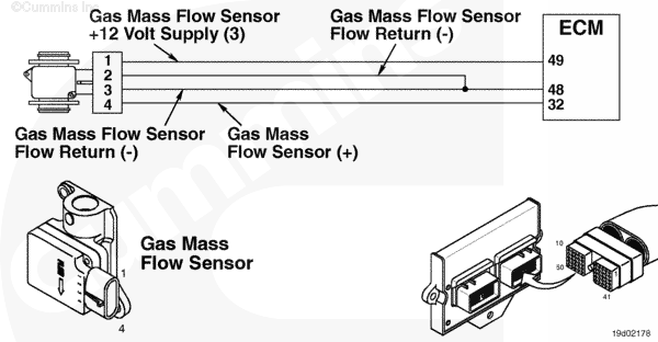
Gas Mass Flow Sensor Circuit |
 |
;)
;)
Circuit Description
The electronic control module (ECM) uses the gas mass flow sensor to measure fuel into the engine and to adjust the fuel control valve based on this measurement. The gas mass flow sensor is powered by battery voltage.
Component Location
The gas mass flow sensor is located on the fuel housing and is unique to the C Series gas engines. On the B and B Gas Plus engines the gas mass flow sensor is located on the fuel control housing.
Shop Talk
The voltage supply for the C Gas Plus engine must be maintained at or above 13.5 VDC for proper sensor operation. On the B and B Gas Plus engines, the voltage must be maintained above 12 VDC for proper sensor operation. This can be monitored in INSITE™ monitoring sensor supply number 3. The possible fail modes are the following: Improper fuel pressure or out of fuel, a stuck or sticking fuel control valve not correcting gas flow according to gas mass flow sensor, restriction due to deposits in the laminar flow screen and oil contamination in the mixer housing and gas flow sensor.
Troubleshooting Steps
| STEPS | SPECIFICATIONS | |
|---|---|---|
| STEP 1. | Check the fault codes. | |
| STEP 1A. Check for active Fault Codes 455 and 511. | Fault Codes 455 and 511 active? | |
| STEP 1B. Check for an inactive fault code. | Fault Code 751 inactive? | |
| STEP 2. | Check the fuel system. | |
| STEP 2A. Check the fuel supply | Fuel supply sufficient? | |
| STEP 2B. Check the primary fuel inlet pressure. | Fuel pressure between 517 to 1138 kPa [75 to 165 psia]? | |
| STEP 2C. Check the secondary fuel inlet pressure. | Is pressure correct for the engine family? | |
| STEP 2D. Check for a stuck open or sticking fuel control valve. | Secondary fuel pressure drop within 50 seconds of key on? | |
| STEP 2E. Check the laminar flow screen. | Deposits or evidence of oil? | |
| STEP 2F. Check for oil in the air fuel mixer housing. | Evidence of oil? | |
| STEP 3. | Clear the fault codes. | |
| STEP 3A. Disable the fault code. | Fault Code 751 inactive? | |
| STEP 3B. Clear the inactive fault codes. | All fault codes cleared? | |
Guided Step 1 – Check the fault codes.
| Guided Step 1A – Check for Fault Codes 455 and 511 for being active. | |
|---|---|
Conditions
ActionCheck for an active 455 and 511 fault code.
|
|
|
Fault Code 455 or 511 active? |
|
| YES | NO |
| No Repair | No Repair |
|
Fault Codes 455 or 511
|
|
| Guided Step 1B – Check for an inactive fault code. | |
|---|---|
Conditions
ActionCheck for an inactive fault code.
|
|
|
Fault Code 751 inactive? |
|
| YES | NO |
| No Repair | No Repair |
|
Procedure 019-362
|
|
Guided Step 2 – Check the fuel system.
| Guided Step 2A – Check the fuel supply. | |
|---|---|
Conditions
ActionCheck the vehicle’s fuel supply.
|
|
|
Fuel supply sufficient? |
|
| YES | NO |
| No Repair |
Refuel the vehicle. |
| Guided Step 2B – Check the primary fuel inlet pressure. | |
|---|---|
Conditions
ActionMonitor the primary fuel pressure.
Note: All pressure sensors on the C8.3G Plus engine are absolute pressure sensors. |
|
|
Fuel pressure between 517 to 1138 kPa [75 to 165 psi]? |
|
| YES | NO |
| No Repair |
Replace the primary regulator. Refer to the OEM troubleshooting and repair manual. |
| Guided Step 2C – Check the secondary fuel inlet pressure. | |
|---|---|
Conditions
ActionMonitor the secondary fuel pressure.
B Gas Plus – 414 kPa [60 psi] B LPG Plus – 276 kPa [40 psi] C Gas Plus – 517 kPa [75 psia] Note: All pressure sensors on the Gas Plus engines are absolute pressure sensors. |
|
|
Is pressure correct for the engine family? |
|
| YES | NO |
| No Repair |
Replace the secondary regulator. Refer to Procedures 005-047 in the B5.9g, B5.9 LPG, B Gas Plus and B LPG Plus Troubleshooting and Repair Manual, Bulletin 3666164 and 005-047 in the C8.3g, C Gas Plus and L Gas Plus Troubleshooting and Repair Manual, Bulletin 3666206. |
| Guided Step 2D – Check for a stuck or sticking fuel control valve. | |
|---|---|
Conditions
ActionCheck for a stuck fuel control valve.
Note: If the fuel control valve is stuck open, raw fuel will be dumped into the engine and out the exhaust. This will cause the gas mas flow sensor to read more fuel than is commanded by the ECM. This will allow Fault Code 751 to occur, but the fuel control valve is actually the root cause. |
|
|
Secondary fuel pressure drop within 50 seconds of keyswitch on? |
|
| YES | NO |
|
A defective fuel control valve has been detected. Replace the fuel control valve. Refer to Procedure 019-102. Use INSITE™ electronic service tool, to reset the fuel tables. |
No Repair |
| Guided Step 2E – Check the laminar flow screen. | |
|---|---|
Conditions
ActionCheck for deposits on the laminar flow screen.
|
|
|
Deposits or evidence of oil? |
|
| YES | NO |
|
Replace the fuel shutoff valve. Refer to Procedure 019-050. |
No Repair |
| Guided Step 2F – Check for oil in the air fuel mixer housing. | |
|---|---|
Conditions
ActionCheck for oil in the air fuel mixer housing and on the sensor components.
Note: Check the fuel filter for excess oil due to improper maintenance. If there is more than one ounce of oil in the fuel filter, there is a possibility that oil has contaminated the fuel system. The customer will need to check their gas compression station for oil carry over. |
|
|
Evidence of oil? |
|
| YES | NO |
|
Replace the gas mass flow sensor. Refer to Procedure 019-101. Clean the fuel system Refer to Procedures 005-009 and 005-047 in the B5.9g, B5.9 LPG, B Gas Plus and B LPG Plus Troubleshooting and Repair Manual, Bulletin 3666164 and Procedures 005-009 and 005-047 in the C8.3g, C Gas Plus and L Gas Plus Troubleshooting and Repair Manual, Bulletin 3666206. Use INSITE™ electronic service tool, to reset the fuel tables. |
No Repair |
Guided Step 3 – Clear the fault codes.
| Guided Step 3A – Disable the fault code. | |
|---|---|
Conditions
ActionDisable the fault code.
|
|
|
Fault Code 751 inactive? |
|
| YES | NO |
| No Repair |
Return to the troubleshooting steps or contact a local Cummins Authorized Repair Location if all steps have been completed and checked again. |
| Guided Step 3B – Clear the inactive fault codes. | |
|---|---|
Conditions
ActionClear the inactive fault codes.
|
|
|
All fault codes cleared? |
|
| YES | NO |
| No Repair |
Troubleshoot any remaining active fault codes. |
|
Repair complete
|
Appropriate troubleshooting charts
|