|
Engine Misfire for Multiple Cylinders – Data Valid but Below Normal Operational Level – Least Severe Level
|

Overview
| CODE | REASON | EFFECT |
| Fault Code: 1482 PID: None SPN: 1322 FMI: None LAMP: None SRT: |
Engine Misfire for Multiple Cylinders – Data Valid but Below Normal Operational Level – Least Severe Level |
None – information for misfire. |
|
Ignition Timing Signal Circuit |
 |
;)
;)
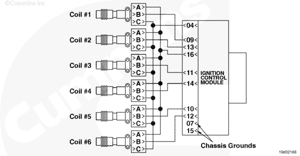
Circuit Description
The ignition control module (ICM) is a distributorless ignition module that provides a signal to the coils and delivers high voltage to the spark plugs. The electronic control module (ECM) controls the ICM by providing ignition timing information. The ICM is capable of misfire and spark voltage detection.
Component Location
The ICM is located next to the ECM on the side of the engine.
Troubleshooting Steps
| STEPS | SPECIFICATIONS | |
|---|---|---|
| STEP 1. | Check the status of misfire. | |
| STEP 1A. Check for an inactive fault code. | Fault Codes 1482 inactive? | |
| STEP 1B. Check for spark plug voltage fault codes. | Fault Codes 613, 1649, 1651, or 1652 active? | |
| STEP 1B-1. Check for multiple fuel system fault codes. | ||
| STEP 1C. Check the life of spark plug. | Spark plugs life is between 50 and 1400 hours? | |
| STEP 2. | Check the ignition coils and spark plugs. | |
| STEP 2A. Inspect the ignition coils and connector pins. | Dirty or damaged pins? | |
| STEP 2B. Check for voltage at the coils. | Steady spark observed? | |
| STEP 2C. Check the spark plugs | Spark plug damaged or wear? | |
| STEP 3. | Check the ICM and ignition harness. | |
| STEP 3A. Inspect ICM, ignition coils and ignition harness connector pins. | Dirty or damaged pins? | |
| STEP 3B. Check for an open circuit in the ignition harness. | Less than 10 ohms? | |
| STEP 3B-1. Check for an open circuit in the ignition harness. | ||
| STEP 3C. Check for a pin short circuit to ground. | Greater than 100k ohms? | |
| STEP 3D. Check for a pin to pin short circuit in the ignition harness. | Greater than 100k ohms? | |
| STEP 3E. Check the ICM. | ICM to specification? | |
| STEP 3F. Verify that ignition coils and ignition circuit are good. | Steady spark observed? | |
| STEP 4. | Clear the fault code. | |
| STEP 4A. Disable the fault code. | Fault Code 1482 inactive? | |
| STEP 4B. Clear the inactive fault codes. | All fault codes cleared? | |
Guided Step 1 – Check status of misfire.
| Guided Step 1A – Check for an inactive fault code. | |
|---|---|
Conditions
Action
|
|
|
Fault Code 1482 inactive? |
|
| YES | NO |
| No Repair | No Repair |
| Guided Step 1B – Check for spark plug voltage fault codes. | |
|---|---|
Conditions
Action
|
|
|
Fault Codes 613, 1649, 1651, or 1652 active? |
|
| YES | NO |
| No Repair | No Repair |
|
Fault Codes 613, 1649, 1651, or 1652 before proceeding
|
|
| Guided Step 1B-1 – Check for multiple fuel system fault codes. | |
|---|---|
Conditions
Action
|
|
|
Fault Codes 2184, 2219, 751, or 752 active? |
|
| YES | NO |
|
Troubleshoot any remaining fault codes before proceeding. Note: If any of these fault coders are present, then the misfire can be due to a system error. Such as, engine running lean or gas mass flow sensor or heated oxygen sensor can not compensate correctly. |
No Repair |
|
Fault Codes 2184, 2219, 751, or 752 before proceeding
|
|
| Guided Step 1C – Check the life of spark plugs. | |
|---|---|
Conditions
Action
|
|
|
Spark plugs life is between 50 and 1400 hours? |
|
| YES | NO |
| No Repair | No Repair |
Guided Step 2 – Check the ignition coils and spark plugs.
| Guided Step 2A – Inspect ignition coil and connector pins. | |
|---|---|
Conditions
Action
For general inspection techniques, refer to Component Connector and Pin Inspection, Procedure 019-361. |
|
|
Dirty or damaged pins? |
|
| YES | NO |
|
A defective connection has been detected in the ignition coil or ignition harness connectors. Repair the damaged pins. Repair or replace the harness, whichever has the damaged pins. |
No Repair |
| Guided Step 2B – Check for voltage at the coils. | |
|---|---|
Conditions
Action
|
|
|
Steady spark observed? |
|
| YES | NO |
| No Repair | No Repair |
| Guided Step 2C – Check the spark plugs. | |
|---|---|
Conditions
Action
|
|
|
Spark plug damage or wear? |
|
| YES | NO |
|
Replace each damaged spark plug. Refer to Procedure 013-016 in the Troubleshooting and Repair Manual C8.3G, C Gas Plus, and L Gas Plus Engines, Bulletin 3666206. |
No Repair |
Guided Step 3 – Check the ICM and ignition harness.
| Guided Step 3A – Inspect the ICM and ignition harness connector pins. | |
|---|---|
Conditions
Action
For general inspection techniques, refer to Component Connector and Pin Inspection, Procedure 019-361. |
|
|
Dirty or damaged pins? |
|
| YES | NO |
|
A defective connection has been detected in the ICM, ignition coils or ignition harness connector. Repair the damaged pins. Repair the harness, whichever has the damaged pins. |
No Repair |
| Guided Step 3B – Check for an open circuit in the ignition harness. | |
|---|---|
Conditions
Action
Refer to the circuit diagram or wiring diagram for connector pin identification. For general resistance measurement techniques, refer to Resistance Measurements Using a Multimeter and Wiring Diagram, Procedure 019-360 |
|
|
Less than 10 ohms? |
|
| YES | NO |
| No Repair |
An open signal circuit has been detected in the ignition harness. Repair or replace the ignition harness.
|
| Guided Step 3B-1 – Check for an open circuit in the ignition harness. | |
|---|---|
Conditions
Action
Note: All spark return signal wires in the ignition harness are tied together. This way there will be continuity through each spark signal pin of each coil to the main spark return signal wire at the ignition harness connector 2. If one of the spark signal circuits is found to be open, then the ICM will think that the engine is misfiring when it is not. Refer to the circuit diagram or wiring diagram for connector pin identification. For general resistance measurement techniques, refer to Resistance Measurements Using a Multimeter and Wiring Diagram, Procedure 019-360 |
|
|
Less than 10 ohms? |
|
| YES | NO |
| No Repair |
A open signal circuit has been detected in the ignition harness. Repair or replace the ignition harness.
|
| Guided Step 3C – Check for a pin short to ground. | |
|---|---|
Conditions
Action
Refer to the circuit diagram or wiring diagram for connector pin identification. For general resistance measurement techniques, refer to Resistance Measurements Using a Multimeter and Wiring Diagram, Procedure 019-360 |
|
|
Greater than 100k ohms? |
|
| YES | NO |
| No Repair |
A pin to ground short circuit has been detected in the ignition harness. Repair or replace the ignition harness.
|
| Guided Step 3D – Check for a pin to pin short circuit in the ignition harness. | |
|---|---|
Conditions
Action
Refer to the circuit diagram or wiring diagram for connector pin identification. For general resistance measurement techniques, refer to Resistance Measurements Using a Multimeter and Wiring Diagram, Procedure 019-360 |
|
|
Greater than 100k ohms? |
|
| YES | NO |
| No Repair |
A pin to pin short circuit has been detected in the ignition harness. Repair or replace the ignition harness.
|
| Guided Step 3E – Check the ICM. | |
|---|---|
Conditions
Action
|
|
|
ICM to specification? |
|
| YES | NO |
| No Repair |
|
| Guided Step 3F – Verify that ignition coils and ignition circuit are good. | |
|---|---|
Conditions
Action
|
|
|
Steady spark observed? |
|
| YES | NO |
| No Repair |
Replace the ignition coil. Refer to Procedure 013-012 in the Troubleshooting and Repair Manual C8.3G, C Gas Plus, and L Gas Plus Engines, Bulletin 3666206. |
Guided Step 4 – Clear the fault codes.
| Guided Step 4A – Disable the fault code. | |
|---|---|
Conditions
Action
|
|
|
Fault Code 1482 inactive? |
|
| YES | NO |
| No Repair | No Repair |
| Guided Step 4B – Clear the inactive fault codes. | |
|---|---|
Conditions
Action
|
|
|
All fault codes cleared? |
|
| YES | NO |
| No Repair | No Repair |
|
Repair complete
|
Appropriate troubleshooting steps
|