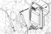
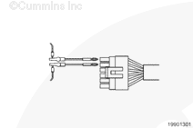
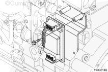
Disconnect the engine harness connector from the ICM. Turn the keyswitch to the ON position.
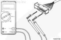
Measure the voltage between the switched battery positive (+) pin and the battery negative (-) pin in the connector. The voltage should be equal to the battery voltage. If the voltage is incorrect, repair or replace the engine harness or the OEM harness.
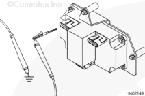
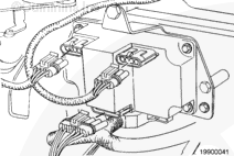
Check for continuity in the wiring harness between the ICM and coils. Turn the keyswitch to the OFF position.
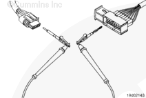
Disconnect the ignition coil harness connector from the ICM. Measure resistance between the ICM pin connectors and the coil connectors as shown in the wiring diagram.
The resistance must be 10 ohms or less. If the resistance is incorrect, repair or replace the wiring harness.
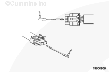
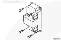
Disconnect the 6-pin connector from the ICM. Turn the keyswitch to the ON position.
Measure the voltage between the switched battery positive (+) pin and the battery negative (-) pin in the connector. The voltage must be equal to the battery voltage. If the voltage is incorrect, repair or replace the engine harness or the OEM harness.
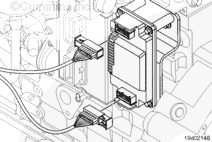
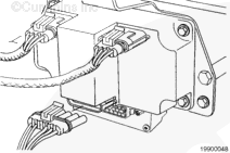
Check for continuity in the wiring harness between the ICM and the coils. Turn the keyswitch to the OFF position.
Disconnect the two 4-pin connectors from the ICM. Measure resistance between the ICM pin connectors and the coil connectors as shown in the wiring diagram.
The resistance must be 10 ohms or less. If the resistance is incorrect, repair or replace the wiring harness.
Hello, I'm Jack, a diesel engine fan and a blogger. I write about how to fix and improve diesel engines, from cars to trucks to generators. I also review the newest models and innovations in the diesel market. If you are interested in learning more about diesel engines, check out my blog and leave your feedback.
View all posts by Jack


;)
;)
;)
;)
;)
;)
;)
;)
;)
;)
;)
;)
;)
;)
;)
;)
;)
;)
;)
;)
;)
;)
;)
;)