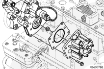
The gear pump shaft incorporates a double seal. The first seals oil in the fuel pump cam housing; the second seals fuel in the gear pump. If either seal fails, fluid will drip from the weep hole. The weep hole is located near the gear pump mounting flange on the inboard side (toward the engine block).
A gear pump gasket seals oil at the gear pump to cam housing interface.
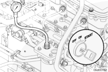
Measuring Gear Pump Pressure with the Engine Cranking (useful if engine will not start).
Install a pressure gauge at the on engine fuel filter head (M10 x 1.5 Compuchek™ fitting, Part Number 3824842).
NOTE: If there is not enough clearance to install the female Compuchek™ fitting, Part Number 3824842, an adapter fitting, Part Number 3932302, and an 1/8-NPT male Compuchek™ fitting, Part Number 3377244, may be used to aid accessibility.
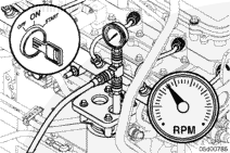
Monitor the gear pump pressure while the engine is cranking.
Minimum Gear Pump Pressure at Cranking
kpa
psi
105
MIN
15
If the gear pump pressure is lower than 105 kPa [15 psi] during cranking, make sure that the engine cranking speed is at least 150 rpm. Make sure that the lift pump pressure during cranking is at least 35 kPa [5 psi]. Refer to Procedure 005-045 in Section 5.
NOTE: For optional test points on the fuel system, a banjo pressure gauge adapter can be constructed.
Construction of Banjo Pressure Gauge Adapter
A banjo-style pressure gauge adapter can be used to measure pressure or vacuum at any point in the low-pressure fuel system where a banjo bolt exists at a fuel line.
The ISC and ISL engines with high-pressure common rail fuel systems use a M12 x 7/16-inch banjo bolt connection. This tool can be used for measurement of drain line restriction (pressure) at the fuel drain manifold.
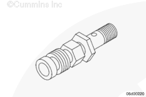
Make a banjo bolt flow adapter tool by drilling and tapping the hex face of an M12 x 7/16-inch banjo bolt, Part Number 3903035 or similar banjo bolt.
Drill and tap the banjo bolt to the size of the Compuchek™ fitting (or other hose union) being used (example 1/8-inch NPT Compuchek™ fitting, Part Number 3377244, or M10 Compuchek™ fitting, Part Number 3824842).
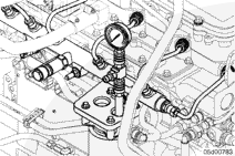
Install a M10 x 1.5 Compuchek™ fitting, Part Number 3824842, at the diagnostic port on the outlet of the fuel filter head.
Construct a “T” adapter fitting using one quick-disconnect, Part Number 3376859, and two 1/8-inch NPT Compuchek™ fittings, Part Number 3042618.
Install a 0.043-inch orificed diagnostic fuel line (Part Number 3164621) at the outlet of the fuel filter head. Run the fuel hose back to the fuel tank.
Install a 0 to 1034 kPa [0 to 150 psi] pressure gauge at the “T” adapter fitting.
Batteries can emit explosive gases. To reduce the possibility of personal injury, always ventilate the compartment before servicing the batteries. To reduce the possibility of arcing, remove the negative (-) battery cable first and attach the negative (-) battery cable last.
WARNING
Depending on the circumstance, diesel fuel is flammable. Keep all cigarettes, flames, pilot lights, arcing equipment, and switches out of the work area and areas sharing ventilation to reduce the possibility of severe personal injury or death when working on the fuel system.
WARNING
Do not vent the fuel system on a hot engine; this can cause fuel to spill onto a hot exhaust manifold, which can cause a fire.
CAUTION
Use caution when disconnecting or removing fuel lines, replacing filters and priming the fuel system that fuel is not spilled or drained into the bilge area. Do not drop or throw filter elements into the bilge area. The fuel and fuel filters must be discarded in accordance with local environmental regulations.
Batteries can emit explosive gases. To reduce the possibility of personal injury, always ventilate the compartment before servicing the batteries. To reduce the possibility of arcing, remove the negative (-) battery cable first and attach the negative (-) battery cable last.
Hello, I'm Jack, a diesel engine fan and a blogger. I write about how to fix and improve diesel engines, from cars to trucks to generators. I also review the newest models and innovations in the diesel market. If you are interested in learning more about diesel engines, check out my blog and leave your feedback.
View all posts by Jack


 WARNING
  CAUTION


;)
;)
;)
;)
;)
;)
;)
;)
;)
;)
;)
;)
;)
;)
;)
;)
;)
;)