Batteries can emit explosive gases. To reduce the possibility of personal injury, always ventilate the compartment before servicing the batteries. To reduce the possibility of arcing, remove the negative (-) battery cable first and attach the negative (-) battery cable last.
WARNING
Fuel is flammable. Keep all cigarettes, flames, pilot lights, arcing equipment, and switches out of the work area and areas sharing ventilation to reduce the possibility of severe personal injury or death when working on the fuel system.
CAUTION
Use caution when disconnecting or removing fuel lines, replacing filters and priming the fuel system that fuel is not spilled or drained into the bilge area. Do not drop or throw filter elements into the bilge area. The fuel and fuel filters must be discarded in accordance with local environmental regulations.
CAUTION
Zinc plugs expand and can break off during removal. Inspect the zinc plug to make sure it is in one piece. If not, it must be replaced with a new zinc plug, and the broken pieces must be retrieved from the aftercooler to prevent damage to components downstream in the sea water system.
Shut off the sea water supply and return line(s). Refer to the OEM service manual.
Shut off the fuel supply and return lines. Refer to the OEM service manual.
Disconnect the battery power from the engine. Refer to Procedure 013-009.
Drain the sea water by removing the zinc anode plug at the bottom of the aftercooler. Refer to Procedure 008-059.
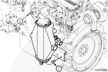
Loosen the aftercooler top and bottom air connection hose clamps.
If necessary, remove the aftercooler air discharge connection. Refer to Procedure 010-131.
Disconnect the aftercooler air inlet connection. Refer to Procedure 010-019.
If necessary, remove the fuel drain flex hoses at the fuel cooler.
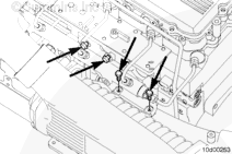
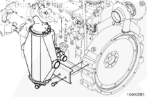
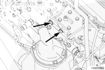
Remove the fuel cooler clip and mounting capscrew.
Remove the fuel cooler lower molded sea water hose from the aftercooler. Support the cooler to prevent damage to the fuel lines.
Loosen the hose clamp on the upper water transfer connection and remove the aftercooler sea water discharge hose.
Batteries can emit explosive gases. To reduce the possibility of personal injury, always ventilate the compartment before servicing the batteries. To reduce the possibility of arcing, remove the negative (-) battery cable first and attach the negative (-) battery cable last.
WARNING
Fuel is flammable. Keep all cigarettes, flames, pilot lights, arcing equipment, and switches out of the work area and areas sharing ventilation to reduce the possibility of severe personal injury or death when working on the fuel system.
CAUTION
Use caution when disconnecting or removing fuel lines, replacing filters and priming the fuel system that fuel is not spilled or drained into the bilge area. Do not drop or throw filter elements into the bilge area. The fuel and fuel filters must be discarded in accordance with local environmental regulations.
CAUTION
Zinc plugs expand and can break off during removal. Inspect the zinc plug to make sure it is in one piece. If not, it must be replaced with a new zinc plug, and the broken pieces must be retrieved from the aftercooler to prevent damage to components downstream in the sea water system.
Shut off the sea water supply and return lines. Refer to the OEM service manual.
Shut off the fuel supply and return lines. Refer to the OEM service manual.
Disconnect the batteries. Refer to Procedure 013-009.
Drain the sea water system by removing the plugs at the bottom of the marine gear oil and fuel cooler.
Remove the aftercooler air box drain plug and drain the condensation from the aftercooler housing core.
Remove the air crossover and air outlet tube. Refer to Procedure 010-019.
Remove the sea water lines. Refer to Procedure 008-056.
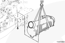
Remove the marine gear oil and fuel cooler assembly. Refer to Procedure 008-129.
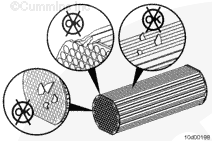
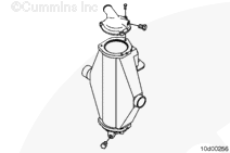
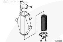
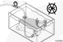
The aftercooler core assembly will slide out of the cooler housing when removing the lower aftercooler water connection. To reduce the possibility of damaging the core, lay the aftercooler assembly on its side to remove the connection and the core.
Lay the aftercooler assembly on its side.
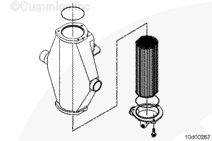
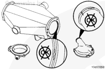
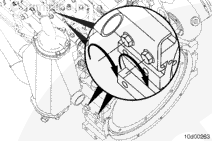
The core assembly has two flat sides which must be orientated toward the aftercooler air intake and outlet sides of the aftercooler.
Assemble the aftercooler in a vertical position. Install the aftercooler core into the aftercooler housing. Align the marks so one flat side of the core is facing the air inlet side of the housing.
Install a new o-ring around the lower core O.D. Install the water end cap and tighten the capscrews.
Torque Value: 43 n.m [32 ft-lb]
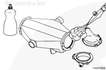
Install a new o-ring around the upper core O.D. Install the water end cap and tighten the capscrews.
Hello, I'm Jack, a diesel engine fan and a blogger. I write about how to fix and improve diesel engines, from cars to trucks to generators. I also review the newest models and innovations in the diesel market. If you are interested in learning more about diesel engines, check out my blog and leave your feedback.
View all posts by Jack
 WARNING
  CAUTION







;)
;)
;)
;)
;)
;)
;)
;)
;)
;)
;)
;)
;)
;)
;)
;)
;)
;)
;)
;)
;)
;)
;)
;)
;)
;)
;)
;)