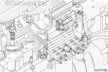
The fueling actuators control the delivery of fuel to the engine. They are a part of the fuel delivery housing, located on the left side of the engine. There are two fueling actuators, one front and one rear.
The front fueling actuator is located on the fuel delivery housing. It is the actuator closest to the front of the engine.
The rear fueling actuator is located on the fuel delivery housing. It is the actuator closest to the rear of the engine.
Perform the INSITE™ electronic service tool Cylinder Performance Test to determine if an actuator has malfunctioned. If a bank malfunctions, this could indicate an actuator malfunction.
If only two injectors in a bank malfunction, repeat the test. Swap the front and rear fueling actuators to determine if the malfunctioned bank of cylinders follows the actuator. If so, replace the malfunctioned fueling actuator as necessary.
If not, swap the front and rear timing actuator to determine if the malfunctioned bank of cylinders follows the actuator. If so, replace malfunctioned timing actuator as necessary.
To perform the priming procedure, use the following items to fabricate a fuel bypass hose:
2 -Quick-disconnect fittings, Part Number 3376859
A length of clear tubing capable of 2758 kPa [400 psi]
Install the fuel bypass hose fabricated above between the suction-side Compuchek™ fitting at the top of the IFSM and the fuel pump Compuchek™ fitting located on the head of the fuel pump. Connect the clear hose and shutoff valve normally used to check for air in fuel to the rail Compuchek™ fitting. Refer to Procedure 006-003 in Section 3. Place the open end in a suitable, clean container and fully open the shutoff valve in the hose.
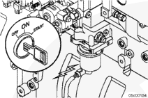
Fill the fuel filter by turning the ignition switch to the ON position; but do not start the engine. The fuel lift pump should begin operating. Monitor the open end of the bleed line from the rail Compuchek™ fitting. When fuel is seen coming out of this line, turn the ignition off. Remove the bleed line and air in fuel test line.
Hello, I'm Jack, a diesel engine fan and a blogger. I write about how to fix and improve diesel engines, from cars to trucks to generators. I also review the newest models and innovations in the diesel market. If you are interested in learning more about diesel engines, check out my blog and leave your feedback.
View all posts by Jack


;)
;)
;)
;)
;)
;)
;)
;)
;)
;)