System Operation Description:
Use this procedure under the following situation:
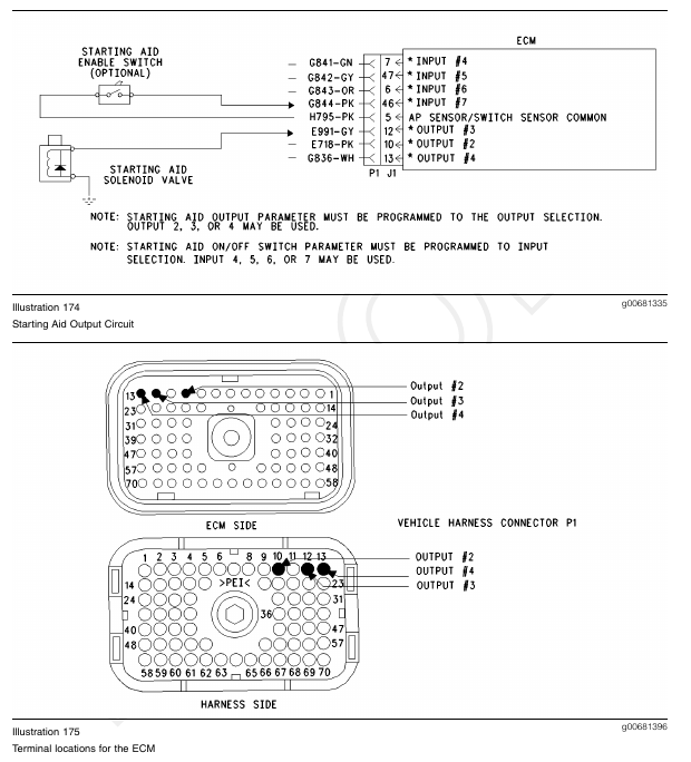
Test Step 1. Check the Electrical Connectors and the Wiring
A. Thoroughly inspect the ECM Vehicle Harness Connector J1/P1, and the firewall bulkhead connectors. Refer to Troubleshooting, “Electrical Connectors – Inspect” for details.
B. Perform a 45 N (10 lb) pull test on terminal 10, terminal 12, or terminal 13 in the ECM connector.
C. Check the ECM connector (allen head screw) for the proper torque of 6.0 N·m (55 lb in).
D. Check the harness and the wiring for abrasion and pinch points from the relays to the ECM.
Expected Result:
All connectors, pins, and sockets are completely coupled and/or inserted, and the harness and wiring should be free of corrosion, abrasion or pinch points.
Results:
• OK – Proceed to Test Step 2.
• Not OK – Repair the wiring or replace the wiring, if necessary. Repair the connectors or replace the connectors, if necessary. Ensure that all of the seals are in the proper place. Ensure that all of the connectors are connected properly. Verify that the repair eliminates the problem. STOP.
Test Step 2. Ensure Correct Parameter Programming
A. Connect the Caterpillar Electronic Technician (ET) to the cab data link connector.
B. Turn the ignition key switch to the ON position.
C. Access the Customer Specified Parameter Screen in order to make sure that the ECM is programmed to use the starting aid output.
D. Ensure that the starting aid circuit is connected to the programmed output.
Expected Result:
The circuit is connected to the correct ECM terminal that is selected for the “Starting Aid Output”.
Results:
• OK – Proceed to Test Step 3.
• Not OK – Update the customer specified parameter in order to match the correct output terminal. Proceed to Test Step 3.
Test Step 3. Check the Relay on ET
A. Turn the ignition key switch to the ON position.
B. Access the “Starting Aid Output Special Test” on ET. The “Starting Aid Output Special Test” will enable the “Starting Aid Output” when the test is active.
Disconnect the starting aid canister in order to prevent accidental discharge.
C. Begin the “Starting Aid Output Special Test” and listen for the solenoid or the relay to “click”. You may need to be near the engine in order to hear the “click”.
Expected Result:
The solenoid or the relay activates when the special test is enabled.
Results:
• OK – The ECM and vehicle components are operating correctly. Ensure that the ether canister is not empty. STOP.
• Not OK – Proceed to Test Step 4.
Test Step 4. Check the ECM on ET
A. Connect ET to the cab data link connector.
B. Turn the ignition key switch to the OFF position.
C. Disconnect the ECM vehicle harness connector J1/P1.
D. Install a 70 Terminal breakout T between connectors J1 and P1.
E. If the “Starting Aid Output” is programmed to J1/P1:10, connect a voltage test lamp to terminal 10 (Output 2) and terminal 65 (-Battery) of the breakout T.
F. If the “Starting Aid Output” is programmed to J1/P1:12, connect a voltage test lamp to terminal 12 (Output 3) and terminal 65 (-Battery) of the breakout T.
G. If the “Starting Aid Output” is programmed to J1/P1:13, connect a voltage test lamp to terminal 13 (Output 4) and terminal 65 (-Battery) of the breakout T.
H. Turn the ignition key switch to the ON position.
I. Access the “Starting Aid Output Special Test” on ET.
J. Cycle the corresponding “Starting Aid Output Special Test” to the ON position and to the OFF position and watch the voltage test lamp.
K. Stop the “Starting Aid Output Special Test”.
Note: A multimeter can not be used in place of the voltage test lamp when the ECM outputs are being tested.
Note: The “Starting Aid Output Special Test” will only remain active for one second in order to prevent accidental discharge. The test lamp will turn off when the “Starting Aid Output Special Test” is disabled.
Expected Result:
The voltage test Lamp will turn ON when the “Starting Aid Output Special Test” is active. The voltage test lamp will turn off when the “Starting Aid Output Special Test” is disabled.
Results:
• OK – The ECM is OK. The problem is in the vehicle wiring. Inspect the vehicle wiring and then repair the vehicle wiring. Otherwise, send the vehicle to the OEM dealer for repair. Verify that the original condition is resolved. STOP.
• Not OK – Temporarily connect a test ECM. Use the “Starting Aid Output Special Test” on ET to check the ECM. If the problem is resolved with the test ECM, install the suspect ECM. If the problem returns with the suspect ECM, replace the ECM. Verify that the repair eliminates the problem. STOP.