M11 Series – Service Manual – 008-062   Water Pump

Remove

TOC

 WARNING 

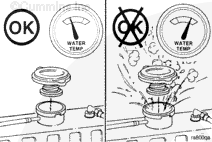
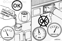
Do not remove the pressure cap from a hot engine. Wait until the coolant temperature is below 50°C [120°F] before removing the pressure cap. Heated coolant spray or steam can cause personal injury.

Remove the pressure cap when the engine is cool.

SMALL | MEDIUM | LARGE


Drain the cooling system. Refer to Procedure 008-018.

SMALL | MEDIUM | LARGE


Remove the alternator drive belt. Refer to Procedure 013-005.

NOTE: Make sure the puller capscrews are threaded all the way through the puller before applying pressure to the puller screw.

Remove the water pump pulley retaining capscrew.

Use the standard pulley puller, Part Number ST-647, or equivalent, and two 5/16 x 18-2 capscrews to remove the pulley.

SMALL | MEDIUM | LARGE


Remove the alternator. Refer to Procedure 013-001.

SMALL | MEDIUM | LARGE


Remove the dust seal.

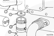
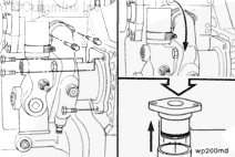
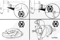
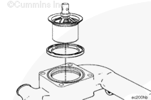
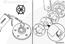
Remove the five water pump oil seal capscrews, clamping ring, oil seal, and gasket.

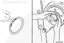
NOTE: Remove the dust seal as the seal carrier is removed; or use a heel bar, or similar tool, to pry the dust seal away from the seal case. Then remove the dust seal by hand.

Discard the oil seal and dust seal.

SMALL | MEDIUM | LARGE


Loosen the coolant bypass hose clamps on both the upper and lower hoses.

Remove the upper coolant hose from the thermostat housing.

SMALL | MEDIUM | LARGE


Remove the four thermostat housing mounting capscrews and the thermostat housing.

SMALL | MEDIUM | LARGE


The coolant flow that provides cooling to the torque converter (if equipped) is achieved in different manners.

M Series engines use a torque converter cooler disc inside the coolant bypass hose to direct engine coolant to the inlet side of the torque converter cooler.

  1. Torque converter coolant supply
  2. Torque converter disc (orifice)
  3. Bypass hose
  4. Water pump.
 
SMALL | MEDIUM | LARGE


Remove the two water pump water transfer connection capscrews.

Remove the three water pump mounting capscrews.

Rotate the water pump outward so the water transfer connection can be removed from the water pump.

Remove the water transfer connection from the water pump.

SMALL | MEDIUM | LARGE


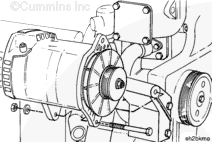
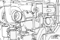
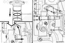
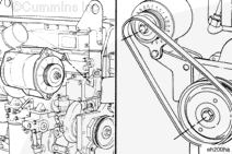
Remove the water pump. Twist the pump outward from the top, and angle the rear of the pump downward as it is being removed to allow the pump to pass the thermostat housing support.

SMALL | MEDIUM | LARGE


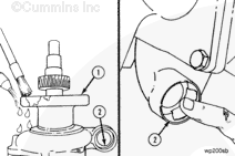
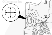
Check the needle bearing for damage and freedom of needle rotation. Replace the bearing if it is damaged or if it does not turn freely.

If the bearing is replaced, use bearing installation tool, Part Number 3824117, or equivalent, along with a cup plug driver to remove the needle bearing from the gear housing. Gently tap the bearing out from the rear side of the housing.

SMALL | MEDIUM | LARGE
   

Clean and Inspect for Reuse

TOC

Clean surfaces (1and 2).

SMALL | MEDIUM | LARGE


Inspect the water pump housing for cracks.

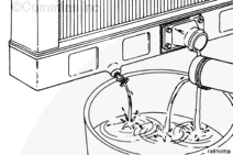
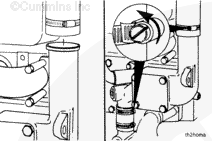
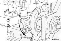
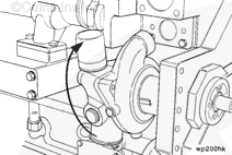
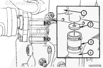
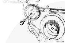
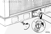
Inspect the water pump weep hole for indication of leaks.

NOTE: A streak or chemical buildup at the weep hole is not justification for water pump replacement. If a steady flow of coolant or oil is observed, replace the water pump with a new or rebuilt unit.

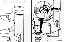
Remove the water pump cover, and inspect the water pump impeller for cracks or damage.

SMALL | MEDIUM | LARGE


If the needle bearing was removed, measure the inside diameter of the gear housing needle bearing bore.

Needle Bearing Bore Inside Diameter (Gear Housing)
mm in
36.967 MIN 1.4553
36.992 MAX 1.4564

SMALL | MEDIUM | LARGE
   

Install

TOC

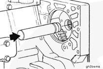
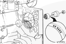
If the needle bearing was removed, use bearing installation tool, Part No. 3824117, to install a new needle bearing in the gear housing.

NOTE: The bearing must be installed with the part number side of the bearing against the installation tool to prevent damage to the bearing during the installation.

Install the bearing from the front side of the gear housing until the bearing is flush with the front edge of the housing bore.

SMALL | MEDIUM | LARGE


Install the water pump cover. Use a new o-ring seal.

Torque Value:  47  n.m  [35 ft-lb]

Install a new o-ring on the water pump mounting flange.

NOTE: The water pump must be twisted outward from the top until the transfer outlet clears the thermostat housing support during installation.

Install the water pump.

SMALL | MEDIUM | LARGE


Install a new o-ring on the water pump water transfer tube.

Install the connection into the water pump.

Twist the water pump inward, and install the three water pump mounting capscrews.

Torque Value:  47  n.m  [35 ft-lb]

Install a new gasket on the water pump water transfer connection. Install and tighten the water transfer connection capscrews.

Torque Value:  25  n.m  [18 ft-lb]

SMALL | MEDIUM | LARGE


If the engine is equipped with a torque converter cooler, install the disc in the bypass hose before installing the thermostat housing.

  1. Torque converter cooler coolant supply
  2. Torque converter cooler disc (orifice)
  3. Bypass hose
  4. Water pump.

SMALL | MEDIUM | LARGE


Install the thermostat in the housing.

Install a new seal in the groove on the thermostat housing mounting surface.

SMALL | MEDIUM | LARGE


Install the hose on the thermostat housing bypass outlet.

Install the thermostat housing and four mounting capscrews.

Torque Value:  54  n.m  [40 ft-lb]

SMALL | MEDIUM | LARGE


Equally space the bypass hose over the water pump connection and thermostat housing connection, and tighten the bypass hose clamps.

Torque Value:  3  n.m  [30 in-lb]

Install the upper and lower coolant hoses. Refer to the OEM service manual for torque specifications.

SMALL | MEDIUM | LARGE


The oil seal must be installed with the lip of the seal and the shaft clean and dry. Do not lubricate. The yellow dust lip must be facing out.

Install the new gasket and oil seal. Use the installation sleeve provided with the new seal to install the seal.

The capscrew threads must be coated with thread sealant, Part Number 3823494, or equivalent, to prevent oil leakage.

Torque Value: Step 1 7 n.m   [60 in-lb]
  Step 2 20 n.m   [180 in-lb]

SMALL | MEDIUM | LARGE


Place a light film of oil or antifreeze on the inside of the oil seal dust seal.

Install the dust seal onto the shaft with the larger outside surface facing the engine.

Push the dust seal back by hand on the shaft until the entire dust seal contacts the oil seal case.

SMALL | MEDIUM | LARGE


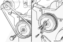
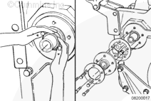
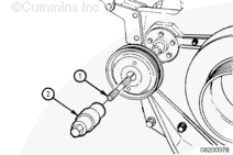
Use the pulley pusher adapter (1), Part Number 3377401, or equivalent, and the pulley pusher (2), Part Number 3376326, or equivalent, to install the pulley.

SMALL | MEDIUM | LARGE


Install the capscrew in the shaft.

Torque Value:  75  n.m  [55 ft-lb]

SMALL | MEDIUM | LARGE


Install the alternator. Refer to Procedure 013-001.

Install and adjust the alternator drive belt. Refer to Procedure 013-005.

SMALL | MEDIUM | LARGE


Close the cooling system draincock, and install the lower coolant hose.

Tighten the hose clamp(s). Refer to the manufacturer’s specifications for the correct torque value.

SMALL | MEDIUM | LARGE


Fill the cooling system. Refer to Procedure 008-018.

Operate the engine until it reaches a temperature of 71°C [160°F] and check for coolant leaks.

SMALL | MEDIUM | LARGE
Last Modified:  10-Dec-2004